
Chemical vapor deposition system

A chemical vapor deposition, wafer carrying technology, applied in the direction of chemical reactive gas, gaseous chemical plating, chemical instruments and methods, etc., can solve the problems of inability to deposit thin films and lowering yields

Inactive Publication Date: 2019-02-05
HERMES EPITEK
View PDF4 Cites 8 Cited by
  • Summary
  • Abstract
  • Description
  • Claims
  • Application Information

AI Technical Summary

Problems solved by technology

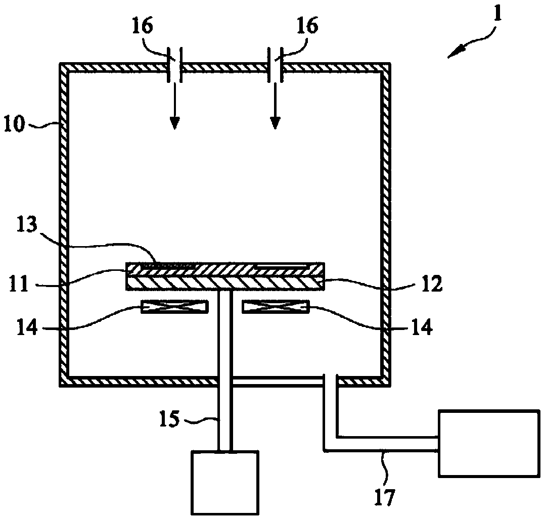
[0007] like image 3 As shown, in the chemical deposition system with the wafer facing down (Face Down), part of the surface of the wafer 24 will be covered by the wafer carrier 21, and the thin film cannot be deposited, thus forming an invalid area, resulting in a reduction in yield

Method used


Image

  • Chemical vapor deposition system
  • Chemical vapor deposition system
  • Chemical vapor deposition system

Examples


Embodiment Construction

[0063] Various embodiments of the present application will be described in detail below, and the accompanying drawings are used as examples. In some embodiments, the examples shown in the figures may be to scale, but in other embodiments, not necessarily to scale. In some embodiments, the same or similar reference numerals may represent the same, similar, or analogous elements and / or elements, but in some embodiments, may also represent different elements. In some embodiments, nouns describing directions may be interpreted literally, but in other embodiments, they may not be interpreted literally. In addition, in order to clearly show certain elements of the present invention, some elements may be omitted in the illustrations. In the description of the specification, many specific details are provided in order to enable readers to have a more complete understanding of the present invention; however, the present invention may still be practiced under the premise of omitting so...


PUM

PropertyMeasurementUnit
widthaaaaaaaaaa

Abstract

In accordance with an embodiment, a chemical vapor deposition system is provided with a susceptor, a plurality of wafer holders, and a processing gas. The susceptor carries the plurality of wafer holders with each bearing a wafer. The susceptor makes revolution around a central axis. The periphery of the wafer includes a chamfer, and each wafer holder includes a protrudent structure having a horizontal bottom surface and an inclined bearing surface to bear the chamfer of the wafer. The processing gas approaches a surface of the wafer and is heated to form a thin film to be deposited on the surface.

Description

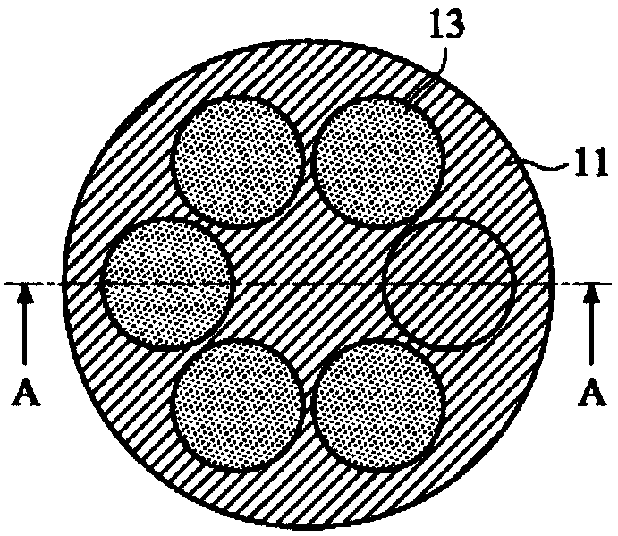
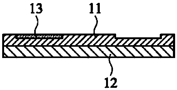
technical field [0001] This case is about a chemical vapor deposition system and its wafer carrier. Background technique [0002] Metal-organic chemical vapor deposition (Metal-Organic Chemical Vapor Deposition, MOCVD), the principle is to use the carrier gas to carry gas phase reactants or precursors into the reaction chamber with the wafer, the carrier under the wafer The susceptor has a heating device to heat the wafer and the gas close to the wafer to increase its temperature, and the high temperature triggers a chemical reaction between a single or several gases, so that the normally gaseous reactants are converted into solids , and deposited on the wafer surface. [0003] US Patent US7670434 discloses a vapor deposition device, figure 1 It is a cross-sectional view showing the vapor deposition device 1 disclosed therein. Such as figure 1 As shown, the vapor deposition apparatus 1 includes a reactor 10, a wafer carrier 11 for carrying a wafer 13, a carrier plate 12 ...

Claims


Application Information

Patent Timeline
Patent Type & Authority Applications(China)
IPC IPC(8): C23C16/458
CPCC23C16/4584H01L21/68735H01L21/6875H01L21/68764C23C16/4585C30B25/10H01L21/68771H01L21/67248C23C16/46C30B25/12C23C16/4583
Inventor 卢柏菁黄冠宁
Owner HERMES EPITEK
Learn More