Method and system for particulate filter regeneration

A particle filter, turbocharger technology, applied in the direction of membrane filter, chemical instruments and methods, transportation and packaging, etc., can solve the problem of insufficient heating of GPF

Pending Publication Date: 2019-02-05
FORD GLOBAL TECH LLC
View PDF1 Cites 10 Cited by
  • Summary
  • Abstract
  • Description
  • Claims
  • Application Information

AI Technical Summary

Problems solved by technology

Spark retardation alone may not be sufficient to heat the GPF

Method used


Image

  • Method and system for particulate filter regeneration
  • Method and system for particulate filter regeneration
  • Method and system for particulate filter regeneration

Examples


Embodiment Construction

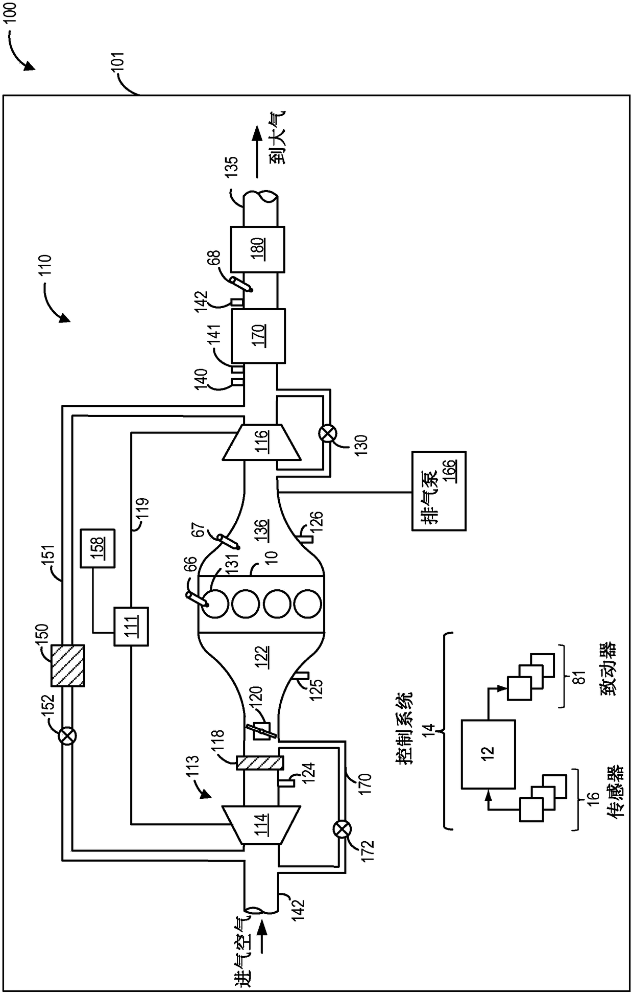
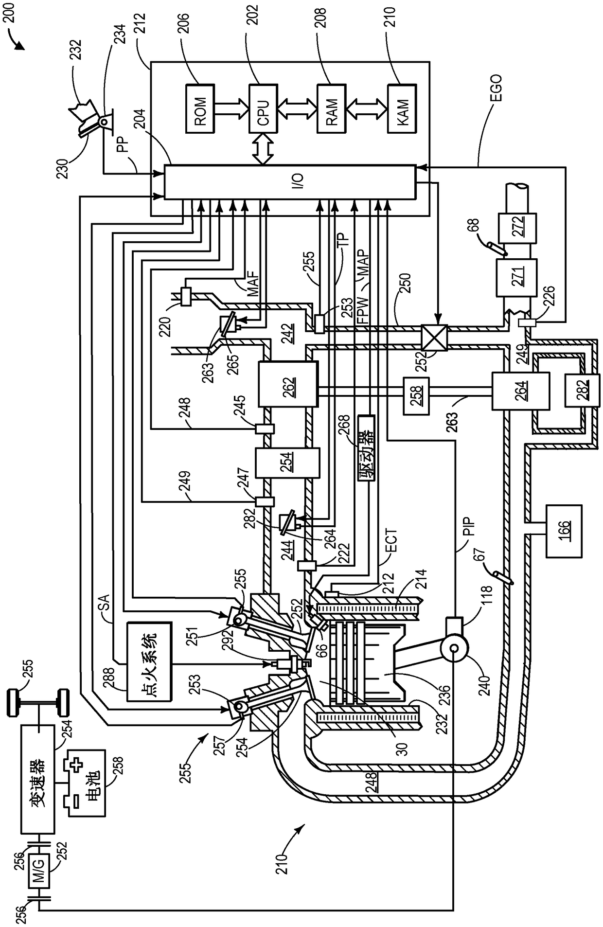
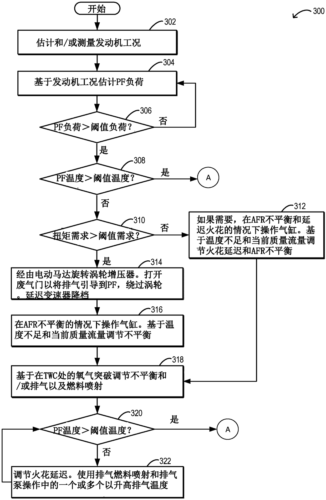
[0015] The following description relates to systems and methods for rapidly heating and frequently regenerating a gasoline particulate filter (GPF) coupled in a turbocharged engine system configured with electric assist, the turbocharged engine systems such as Figure 1-2 engine system. The engine system may further include an exhaust pump and an exhaust fuel injector so that the exhaust air-fuel ratio at the particulate filter can be adjusted differently from the combustion air-fuel ratio at the cylinder. The engine controller can be configured to execute control routines such as Figure 3-4 An example routine to expedite the heating of the particulate filter to an operating temperature where regeneration can be initiated. In particular, the controller may rely on the heat release generated via the cylinder air-fuel imbalance, which is enhanced using air flow regulation provided via the turbocharger. exist Figure 5 A prophetic example of coordinating electric turbocharge...


PUM


Abstract

The present invention relates to a method and a system for particulate filter regulation. Methods and systems are provided for expediting exhaust particulate filter regeneration. In one example, an engine controller may generate an exotherm at the filter by operating engine cylinders with air-fuel imbalance while using electric assist to a turbocharger to meet a torque demand and raise an intake airflow to enhance the effect of the exotherm. Once heated, the filter may be regenerated by flowing extra air to the exhaust via an air pump and injecting extra fuel to an exhaust passage via an exhaust injector.

Description

technical field [0001] The present invention generally relates to methods and systems for effectuating particulate filter regeneration. Background technique [0002] Direct injection engines may provide increased performance so that engine efficiency may be improved. Injecting fuel directly into the cylinder reduces the temperature inside the cylinder so that more air and fuel can be drawn into the cylinder. However, since there is less time to mix the air and fuel, the air-fuel mixture in the cylinder may not completely vaporize when fired at higher engine speeds and loads. As a result, a portion of the injected fuel may be incompletely oxidized, forming carbonaceous soot within the cylinder. After the soot is expelled from the engine, the soot may be stored in the particulate filter for subsequent oxidation. [0003] Some internal combustion engines employ a particulate filter or PF in the exhaust system (e.g., a gasoline particulate filter (GPF) or diesel particulate f...

Claims


Application Information

Patent Timeline
Patent Type & Authority Applications(China)
IPC IPC(8): F01N3/025
CPCF01N3/0253F02D41/008F01N3/323F02D41/025F01N9/002F02D41/123F02D41/1445F02B39/10F02D37/02F02D41/0007F01N2430/06F01N2900/1602F02D2200/0802F02D2200/0812F01N3/0236F02B37/10F02B37/183F02D41/029Y02T10/12Y02T10/40B01D46/84B01D2279/30F01N3/10F01N11/007F02D41/0082F02D41/1446F02P5/145
Inventor T·凯利D·R·马丁J·H·巴克兰J·E·罗林格B·M·罗奇M·J·V·纽斯塔特A·沙阿E·G·塞尔邦
Owner FORD GLOBAL TECH LLC
Why Eureka
Try Eureka