
Semiconductor test structure, manufacturing method and sheet resistance measurement method

A technology of test structure and manufacturing method, which is applied in the direction of semiconductor/solid-state device testing/measurement, semiconductor devices, semiconductor/solid-state device components, etc., and can solve problems such as large limitations, inability to test sheet resistance alone, and inaccurate test results , to achieve the effect of improving precision, eliminating parasitic resistance and wide application range

Active Publication Date: 2020-05-05
成都迈斯派尔半导体有限公司
View PDF10 Cites 0 Cited by
  • Summary
  • Abstract
  • Description
  • Claims
  • Application Information

AI Technical Summary

Problems solved by technology

The existing sheet resistance measurement methods have great limitations. For example, when testing some devices, if the electrodes of the test structure are connected to multi-layer doped layers, then the multi-layer doped layers will form a parallel connection and cannot be tested separately. The sheet resistance of one of the doped layers leads to inaccurate test results

Method used


Image

  • Semiconductor test structure, manufacturing method and sheet resistance measurement method
  • Semiconductor test structure, manufacturing method and sheet resistance measurement method
  • Semiconductor test structure, manufacturing method and sheet resistance measurement method

Examples


Embodiment Construction

[0060] The following will clearly and completely describe the technical solutions in the embodiments of the present invention with reference to the accompanying drawings in the embodiments of the present invention. Obviously, the described embodiments are only some, not all, embodiments of the present invention. The components of the embodiments of the invention generally described and illustrated in the figures herein may be arranged and designed in a variety of different configurations. Accordingly, the following detailed description of the embodiments of the invention provided in the accompanying drawings is not intended to limit the scope of the claimed invention, but merely represents selected embodiments of the invention. Based on the embodiments of the present invention, all other embodiments obtained by those skilled in the art without making creative efforts belong to the protection scope of the present invention.

[0061] It should be noted that like numerals and let...


PUM


Abstract

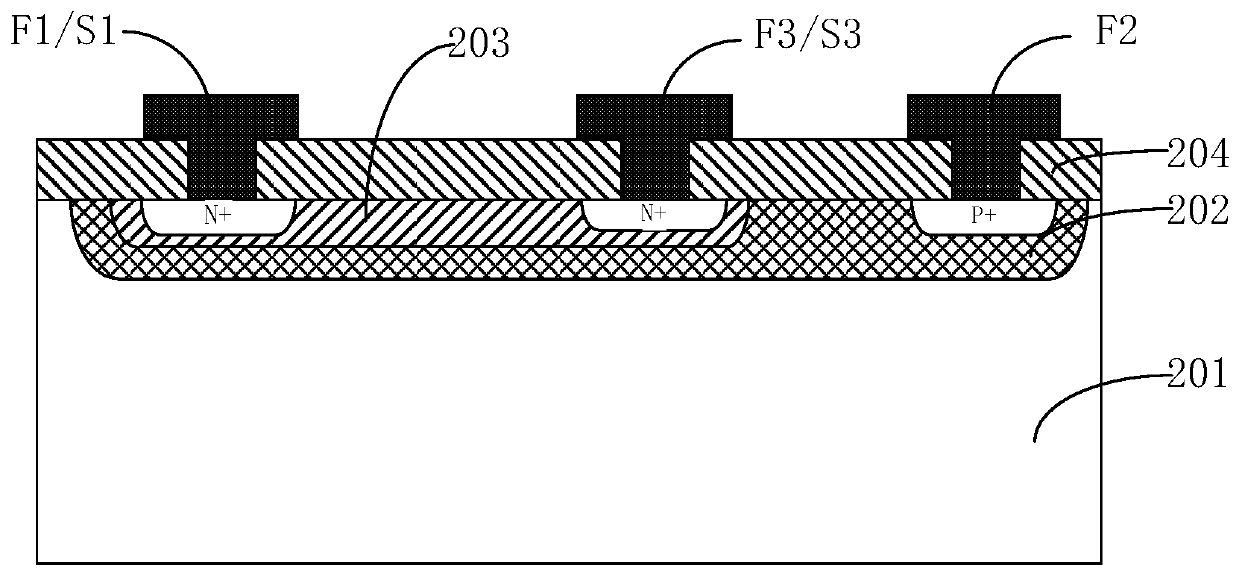
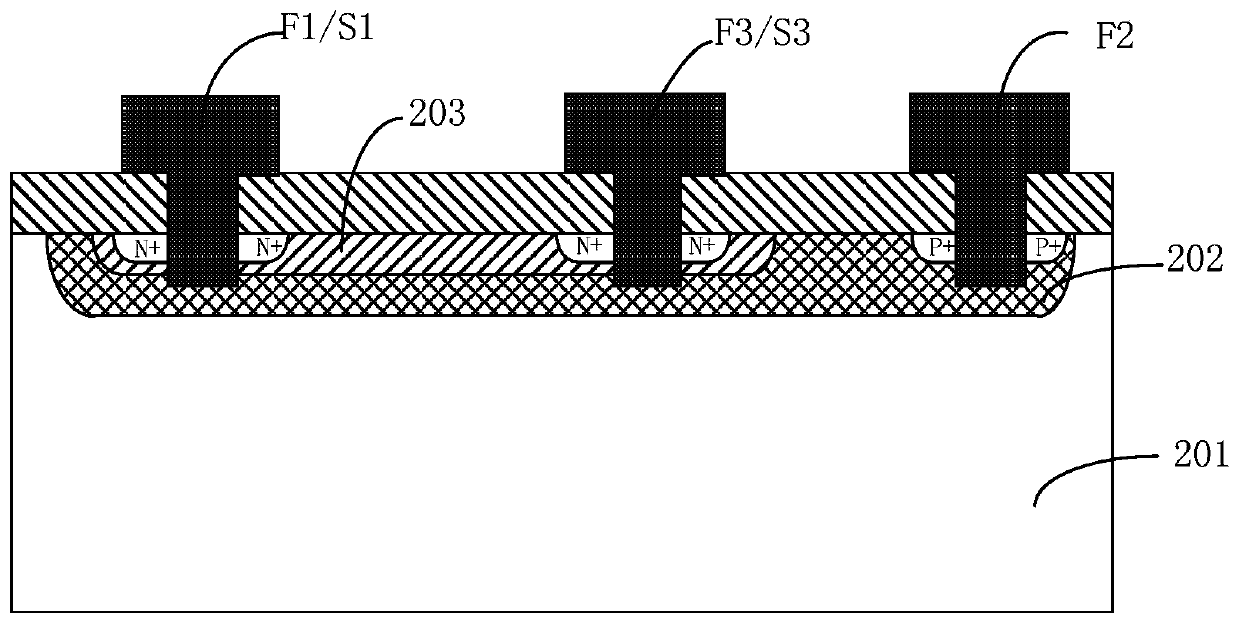
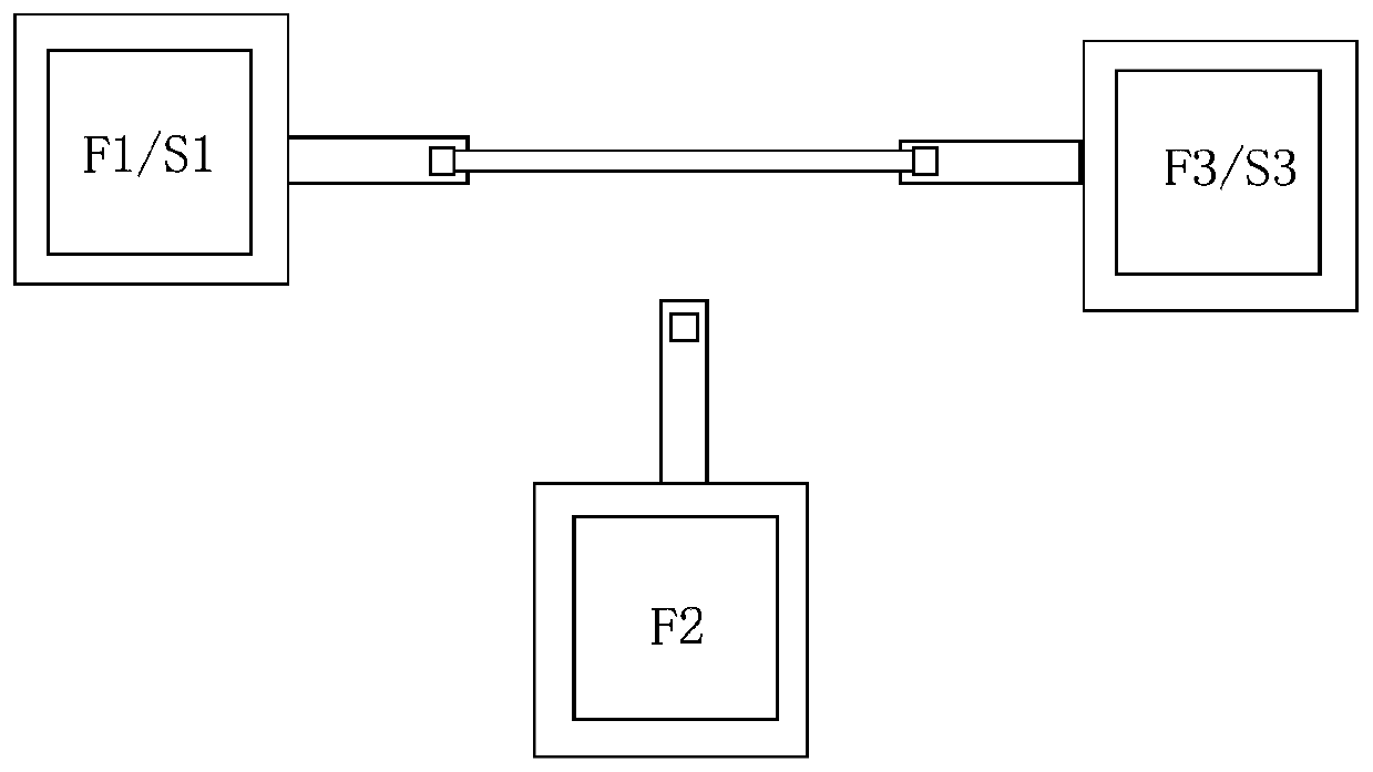
The invention provides a semiconductor test structure and a manufacturing method thereof, and a square resistance measurement method, and relates to the technical field of semiconductors. A first doping layer and a second doping layer can be formed on a substrate; a first electric pole can be formed in the substrate other than the first doping layer and the second doping layer through manufacturing; a second electric pole can be formed in the first doping layer and the second doping layer; and a third electric pole can be formed between the first doping layer and the second doping layer. Whensquare resistance measurement is performed, test current can be applied through the first electric pole and the second electric pole, bias voltage can be applied through the third electric pole, and the third electric pole inverts a channel under appropriate bias voltage, so that the first doping layer can communicate with the second doping layer; and the flow direction of the current can be reasonably arranged according to the conductive types of different doping layers, so that PN junctions between the first doping layer and the second doping layer can be in null bias or slight reverse bias.The second doping layer is in a bypass state during measuring, so that the independent measurement on the square resistance of the first doping layer can be realized, and therefore, square resistancemeasurement precision can be enhanced.

Description

technical field [0001] The invention relates to the technical field of semiconductors, in particular to a semiconductor testing structure, a manufacturing method and a sheet resistance measuring method. Background technique [0002] In integrated circuit and device manufacturing, sheet resistance measurement is widely used for in-line monitoring of specific doped layers to identify possible process fluctuations. For example, by measuring the sheet resistance of a specific doped layer to monitor the size of the ion implantation window, ion implantation dose or energy, diffusion temperature, implantation time, etc., so as to ensure the normal electrical characteristics of the final device and circuit, and the consistency and stability of parameters performance, and device and circuit reliability. The existing sheet resistance measurement methods have great limitations. For example, when testing some devices, if the electrodes of the test structure are connected to multi-layer...

Claims


Application Information

Patent Timeline
Patent Type & Authority Patents(China)
IPC IPC(8): H01L23/544H01L21/66
CPCH01L22/14H01L22/30
Inventor 蒲奎杜文芳曾军穆罕默德·恩·达维希苏世宗
Owner 成都迈斯派尔半导体有限公司
Learn More