
Signal waveform processing method for wireless channel parameter measurement

A wireless channel, parameter measurement technology, applied in transmission monitoring, electrical components, transmission systems, etc., can solve the problem of sacrificing time domain time resolution and additional delay range, scanning frequency response test interval is short, distance expansion cannot be opened, etc. question

Inactive Publication Date: 2019-02-05
STATE KEY LAB OF COMPLEX ELECTROMAGNETIC ENVIRONMENTAL EFFECTS ON ELECTRONICS & INFORMATION SYST
View PDF7 Cites 1 Cited by
  • Summary
  • Abstract
  • Description
  • Claims
  • Application Information

AI Technical Summary

Problems solved by technology

[0014] This method has three main disadvantages: First, because the alignment of the absolute time of the transceiver depends on a high-precision clock (such as a rubidium clock) or GPS timing, the transceiver needs to perform clock synchronization before each measurement, so that the main path signal can be measured absolute delay
[0017] The limitations of this method are: First, the measurement distance is limited. Since the transmitting and receiving antennas need to be connected to the vector network analyzer, the distance cannot be extended, and it is generally only suitable for indoor environment measurement; but the measurement is not real-time
For a time-varying channel, the frequency response changes very quickly, so fast scanning must be used to make the total scanning frequency response test interval as short as possible. To achieve fast scanning, frequency steps must be reduced, which will sacrifice the time resolution of the time domain and the additional delay. scope
In addition, the system needs high-performance instruments such as vector network analyzers and frequency scanners to build, and the cost is relatively high

Method used


Image

  • Signal waveform processing method for wireless channel parameter measurement
  • Signal waveform processing method for wireless channel parameter measurement
  • Signal waveform processing method for wireless channel parameter measurement

Examples


Embodiment Construction

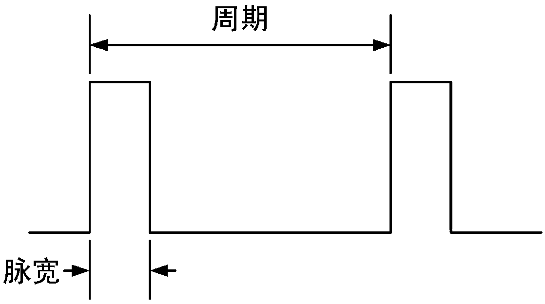
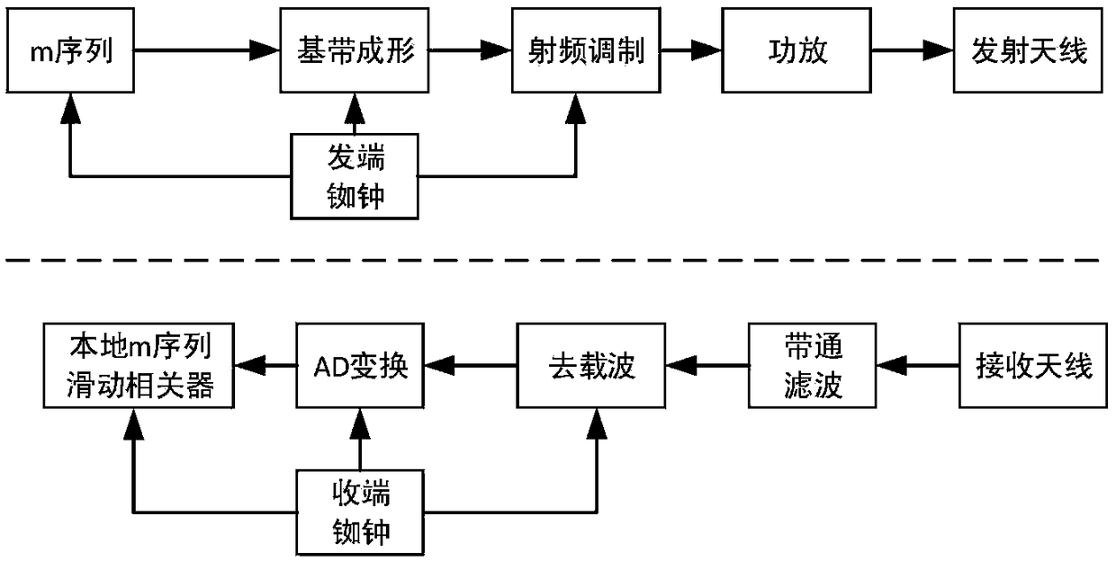
[0084] Such as figure 1 , 2, 3, 4, 5, 6, 7, and 8, the wireless channel measurement signal waveform design method proposed by the present invention is based on the currently commonly used pseudo-random sequence measurement signal design method, and its improved design is carried out. The basic principle of the present invention is to firstly use the GPS or Beidou second pulse signal as the starting reference time for signal transmission, and then divide the time interval of 1 second into pulse signals with equal pulse periods and certain duty ratios according to different scenarios, and use this The pulse signal modulates the periodic pseudo-random sequence, and the signal repetition period is extended without reselecting the pseudo-random sequence, such as the m-sequence, thus producing a variable-period, non-full-duty, self-contained A pulsed pseudo-random sequence signal of the time reference, i.e. a measured transmitted signal such as Figure 5 shown.

[0085] Main tech...


PUM


Abstract

The invention belongs to the technical field of wireless channel measurement and discloses a signal waveform processing method for wireless channel parameter measurement signals. A pulse signal and apseudorandom sequence are combined. A pulse random sequence signal is taken as a signal basic waveform. Framing and sending are carried out according to pulse per second timing information. At a receiving end, synchronous sliding correlation reception is carried out through utilization of second timing information. On the premise that delay measurement precision is not reduced, clock synchronization of a transmitter and a receiver is avoided before measurement each time, measurement delay precision and the maximum measurable delay in different scenes can be freely adjusted, the pseudorandom sequence does not need to be reelected, and the method is relatively applicable to online measurement. The method has the advantages that on the premise that the delay measurement precision is not reduced, the clock synchronization of the transmitter and the receiver is avoided before each time measurement, the measurement delay precision and the maximum measurable delay in different scenes can be freely adjusted, the pseudorandom sequence does not need to be reelected, and the method is applicable to the online measurement.

Description

technical field [0001] The invention belongs to the technical field of wireless channel measurement, and relates to a signal waveform processing method for wireless channel parameter measurement. Background technique [0002] Wireless channel parameter measurement is an important basis for wireless communication system design, system simulation, and communication network planning. The parameters to be measured usually include delay power spectrum, main path absolute delay, main path received power, and multipath relative delay. , multipath relative power, etc. [1]. [0003] Wireless channel parameter measurement can be divided into offline channel measurement and real-time channel measurement according to different requirements for instant acquisition of measurement results. According to different measurement bandwidths, it can be divided into wideband channel measurement and narrowband channel measurement. According to different spatial correlation measurement requirements,...

Claims


Application Information

Patent Timeline
IPC IPC(8): H04B17/309
CPCH04B17/309
Inventor 王满喜李永成郑光勇高磊刘国柱杨晓帆李廷鹏
Owner STATE KEY LAB OF COMPLEX ELECTROMAGNETIC ENVIRONMENTAL EFFECTS ON ELECTRONICS & INFORMATION SYST
Learn More