

High-frequency heating device
A high-frequency heating device and high-frequency technology, applied in the direction of electric heating device, microwave heating, ohmic resistance heating, etc., can solve problems such as complex structure and high power
- Summary
- Abstract
- Description
- Claims
- Application Information
AI Technical Summary
Problems solved by technology
Method used
Image

Examples
Embodiment approach 1
[0055] Next, use figure 1 The high-frequency heating device 100 according to Embodiment 1 will be described.
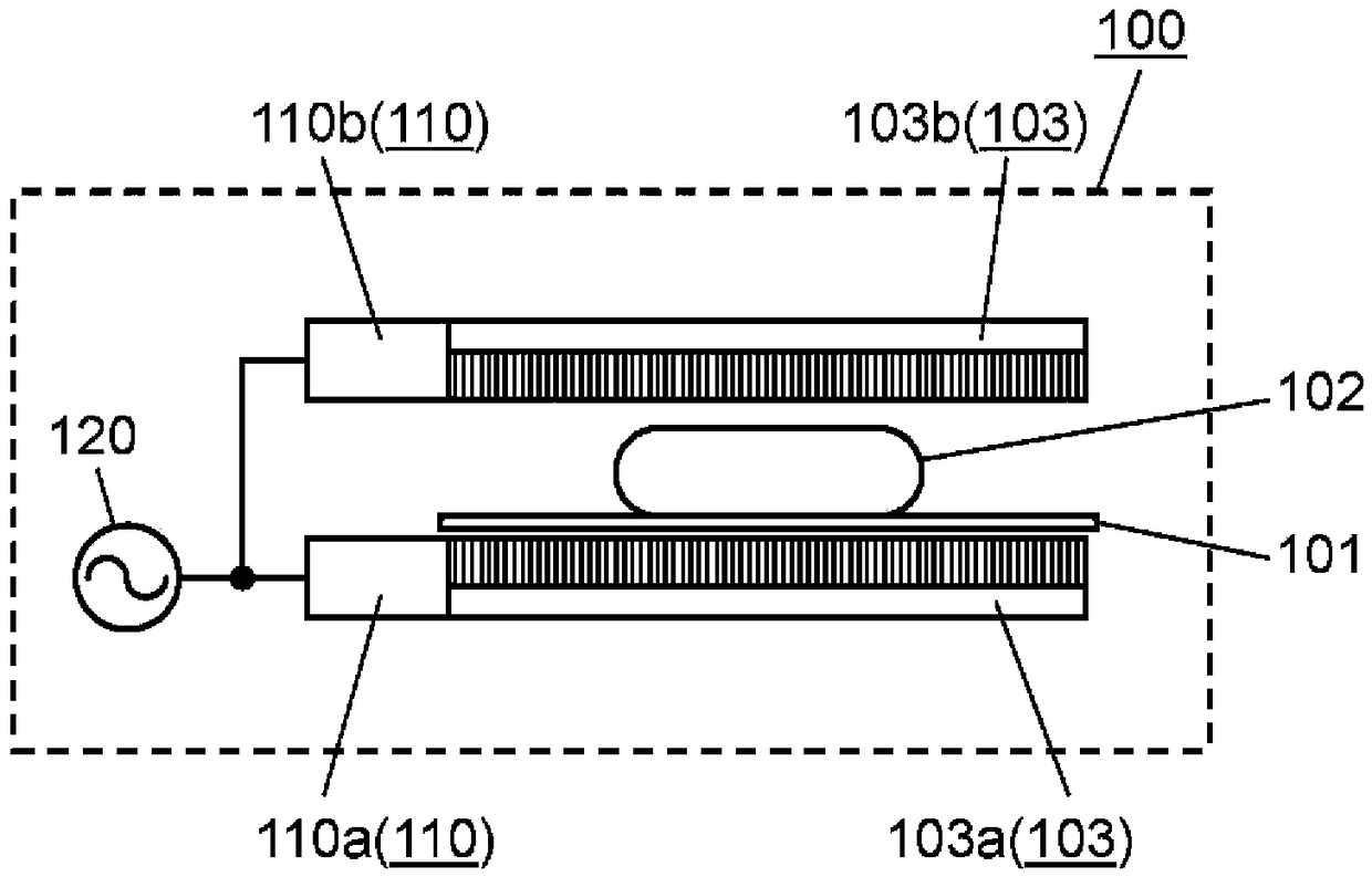
[0056] figure 1 It is a block diagram showing the basic configuration of the high-frequency heating device 100 according to the first embodiment.
[0057] Such as figure 1 As shown, the high frequency heating device 100 has a first surface wave exciter 103a and a second surface wave exciter 103b, a first high frequency power supply part 110a and a second high frequency power supply part 110b, a high frequency power generation part 120 and the setting table 101 on which the object to be heated 102 is placed. The high-frequency heating device 100 heat-processes an object to be heated 102 placed on an installation table 101 .
[0058] The first surface wave exciter 103a and the second surface wave exciter 103b are provided at positions (for example, upper and lower positions) facing each other so as to sandwich the object to be heated 102 . In this case, the upper a...
Embodiment approach 2
[0097] Below, refer to Figure 4 A high-frequency heating device 200 according to Embodiment 2 of the present invention will be described.
[0098] In addition, in the high-frequency heating apparatus 200 of this embodiment, the same reference numeral is attached|subjected to the component which has the same function as Embodiment 1, and description is abbreviate|omitted. In addition, the description of the content having the same effect as that of Embodiment 1 is also omitted.
[0099] Figure 4 It is a block diagram showing the basic configuration of the high-frequency heating device 200 according to the second embodiment.
[0100] Such as Figure 4 As shown, the high-frequency heating device 200 supplies the high-frequency power generated by the high-frequency power generation unit 220 to only the first surface wave exciter 203a via the high-frequency power supply unit 210, which is different from the high-frequency power of the first embodiment in this point. The heati...
Embodiment approach 3
[0116] Below, refer to Figure 6 A high-frequency heating device 300 according to Embodiment 3 of the present invention will be described.
[0117] In addition, in the high-frequency heating apparatus 300 of this embodiment, the same reference numeral is attached|subjected to the component which has the same function as Embodiment 1 or Embodiment 2, and description is abbreviate|omitted. In addition, the description of the content having the same effect as that of Embodiment 1 or Embodiment 2 is also omitted.
[0118] Figure 6 It is a block diagram showing the basic configuration of the high-frequency heating device 300 according to the third embodiment.
[0119] Such as Figure 6 As shown, the high-frequency heating device 300 is supplied from the first high-frequency power generation unit 320a and the second high-frequency power generation unit 320b respectively provided corresponding to the first surface wave exciter 303a and the second surface wave exciter 303b. The hig...
PUM
| Property | Measurement | Unit |
|---|---|---|
| Power consumption | aaaaa | aaaaa |
Abstract
Description
Claims
Application Information