Sand making machine capable of adjusting sand granularity

A sand making machine and sand grain technology, which is applied in the field of sand making machines that can adjust the sand grain size, can solve the problems of large sand grain size, uneven and fine sand grains, etc., and achieve the effect of uniform sand grains, simple structure, and strong practicability

Inactive Publication Date: 2019-02-15
ZAOZHUANG SNKSAN INTELLIGENT MACHINERY CO LTD
View PDF0 Cites 4 Cited by
  • Summary
  • Abstract
  • Description
  • Claims
  • Application Information

AI Technical Summary

Problems solved by technology

However, the particle size of such sand and gravel may still be large, and the sand particles are not uniform and fine.

Method used


Image

  • Sand making machine capable of adjusting sand granularity
  • Sand making machine capable of adjusting sand granularity
  • Sand making machine capable of adjusting sand granularity

Examples


Embodiment 1

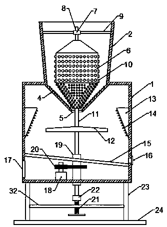
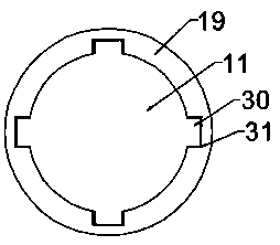
[0021] see Figure 1~3 , in an embodiment of the present invention, a sand making machine that can adjust the sand particle size includes a sand making cylinder 1 and a feeding cylinder 2, and the feeding cylinder 2 is arranged on the upper end of the sand making cylinder 1 and the lower end is connected to the The inside of the sand cylinder 1 is connected, and the diameter of the feed cylinder 2 gradually decreases from top to bottom. The inside of the feed cylinder 2 is provided with a grinding cylinder 6 that coincides with its axis, and the bottom end of the grinding cylinder 6 is fixed. A rotating shaft 11 coaxial with it is connected, and the lower end of the rotating shaft 11 passes through the bottom wall of the sand making cylinder 1, and the outer side of the lower end of the rotating shaft 11 is provided with a rotating sleeve 19, and the outer wall of the rotating sleeve 19 Rotation is installed on the bottom wall of the sand making cylinder 1, and the inner wall ...

Embodiment 2

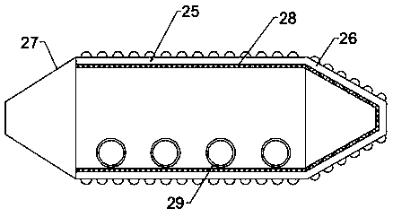
[0025] This embodiment differs from Embodiment 1 in that: the cylinder 25 and the grinding column head 26 are both hollow, and elastic pads 28 are attached to the inside, and a plurality of impact balls 29 are arranged inside the cylinder 25. When the grinding column When the body 6 rotates, the impact balls 29 collide with each other on the side wall of the cylinder 25 and the grinding column head 26, thereby preventing the sand particles from being adsorbed on the outer side wall of the grinding column 6. The fastening mechanism of the cylinder 6, the fastening mechanism includes a guide rod 8 fixed on the top of the grinding cylinder 6, the outer wall of the guide rod 8 is rotatably connected with a plurality of 9, and the other end of the fixed connecting rod 9 is fixed to the feeding cylinder On the side wall of the body 2, the stable rotation of the grinding cylinder 6 can be ensured.


PUM


Abstract

The invention discloses a sand making machine capable of adjusting sand granularity in the technical field of sand making machine. The sand making machine comprises a sand making cylinder body and a feeding cylinder body. A rotating motor is arranged on the inner bottom wall of the sand making cylinder body. Two transmission gears are arranged on an output shaft of the rotating motor and the outerside wall of a rotating casing correspondingly and are meshed with each other. A grinding cylinder body is composed of a grinding column head, a box cover and a cylinder body. A grinding annular conecylinder with a funnel structure is arranged at the communication position between the feeding cylinder body and the sand making cylinder body. The bottom of the grinding annular cone cylinder is provided with a material via opening allowing sand grains to pass through. The outer side wall of the grinding column body and the inner side wall of the grinding annular cone cylinder are provided withgrinding protrusions. The lower side of the sand making cylinder body is provided with a base substrate. Fixing plates are fixedly connected between a plurality of supporting leg columns and providedwith adjusting screw rods spirally matched with the fixing plates. The sand making machine is simple in structure, can adjust the granularity of sand made of gravel to gradually make the sand with even sand grains through grinding, and is convenient to operate and strong in practicability.

Description

technical field [0001] The invention relates to the technical field of sand making machines, in particular to a sand making machine capable of adjusting the grain size of sand. Background technique [0002] Sand making machine is also called crusher. This machine is widely used, not only for medium-hard and extremely hard materials, such as: granite, basalt, limestone, quartz stone, gneiss, cement clinker, concrete aggregate, ceramic raw materials, Iron ore, gold ore, copper ore, corundum, bauxite, silica, etc. It can also be applied to the fine crushing and superfine crushing operations of artificial sand making, pre-ground cement, mining, refractory materials and other industries with great differences in material properties. [0003] In the sand making machine, the material first falls vertically into the high-speed rotating impeller from the upper part of the machine, and then under the action of high-speed centrifugal force, it collides with another part of the materia...

Claims


Application Information

Patent Timeline
Patent Type & Authority Applications(China)
IPC IPC(8): B02C19/20B02C19/00
CPCB02C19/20B02C19/005
Inventor 孙启祥马驰孙法虎
Owner ZAOZHUANG SNKSAN INTELLIGENT MACHINERY CO LTD
Why Eureka
Try Eureka