Online measuring system for high-speed cutting deformation field and method thereof

A high-speed cutting and measurement system technology, applied in the direction of measuring/indicating equipment, metal processing equipment, metal processing machinery parts, etc., can solve complex problems, difficult to guarantee prediction accuracy, limited, and can only analyze to the order of a few meters to a dozen meters Cutting speed and other issues, to achieve the effect of guaranteed processing accuracy, simple structure, and enhanced practicability

Active Publication Date: 2019-02-15
HUAZHONG UNIV OF SCI & TECH
View PDF16 Cites 10 Cited by
  • Summary
  • Abstract
  • Description
  • Claims
  • Application Information

AI Technical Summary

Problems solved by technology

For the high-speed cutting process, some researchers use a high-speed camera to obtain the images before and after the surface deformation of the object, and then match the position of the same pixel in different images to obtain the displacement vector of the pixel, so as to obtain the displacement field of the surface of the specimen, but , the performance of the high-speed camera is limited, and it can only analyze the cutting speed of a few meters to a dozen meters; in addition, the temperature also has a great influence on the cutting deformation. At present, most of the high-speed cutting processes use simulation methods to monitor the temperature. However, such predictions are theoretical, and the actual cutting process is much more complicated than the theory, and the prediction accuracy is difficult to guarantee

Method used


Image

  • Online measuring system for high-speed cutting deformation field and method thereof
  • Online measuring system for high-speed cutting deformation field and method thereof
  • Online measuring system for high-speed cutting deformation field and method thereof

Examples


Embodiment Construction

[0034] In order to make the object, technical solution and advantages of the present invention clearer, the present invention will be further described in detail below in conjunction with the accompanying drawings and embodiments. It should be understood that the specific embodiments described here are only used to explain the present invention, not to limit the present invention. In addition, the technical features involved in the various embodiments of the present invention described below may be combined with each other as long as they do not constitute a conflict with each other.

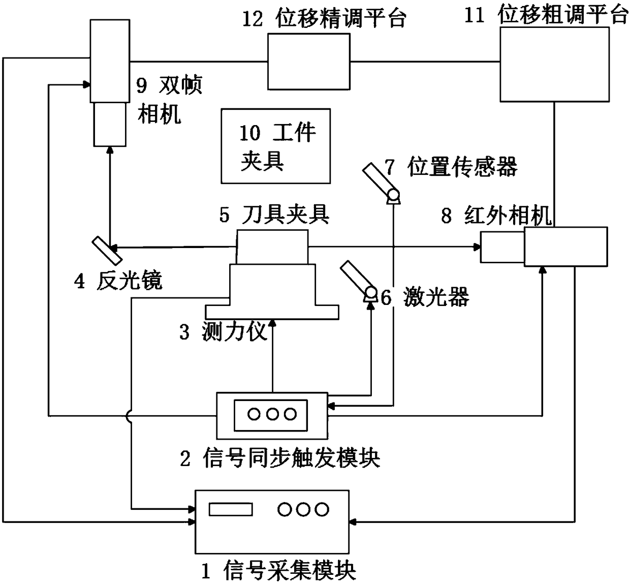
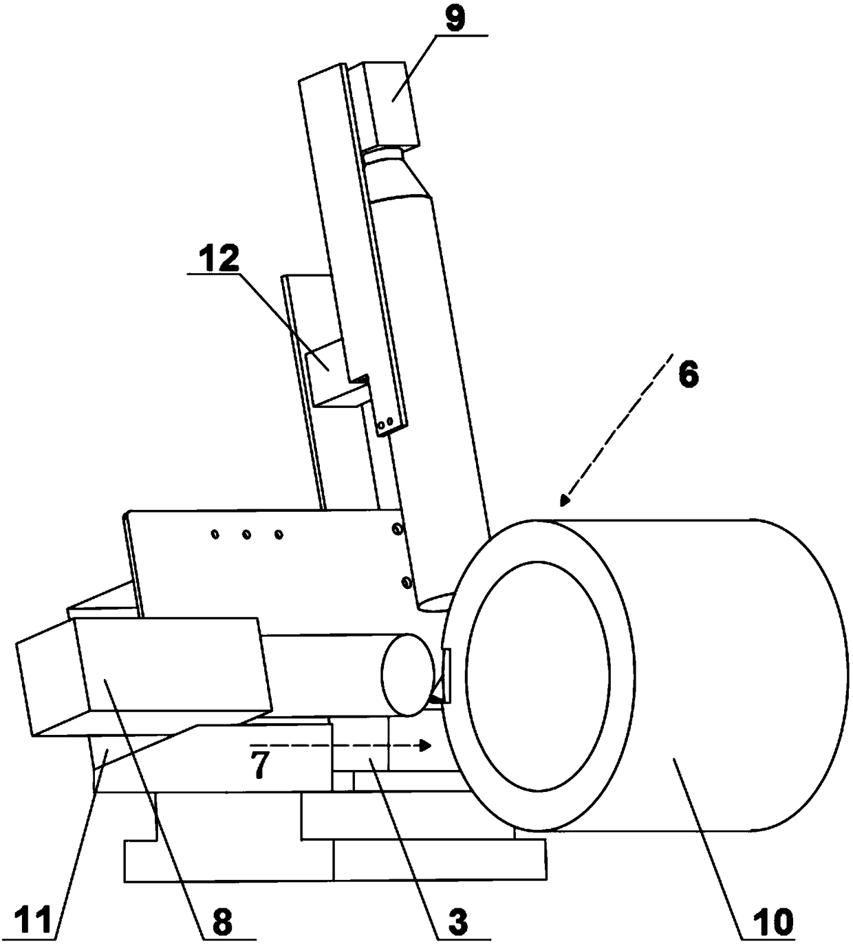
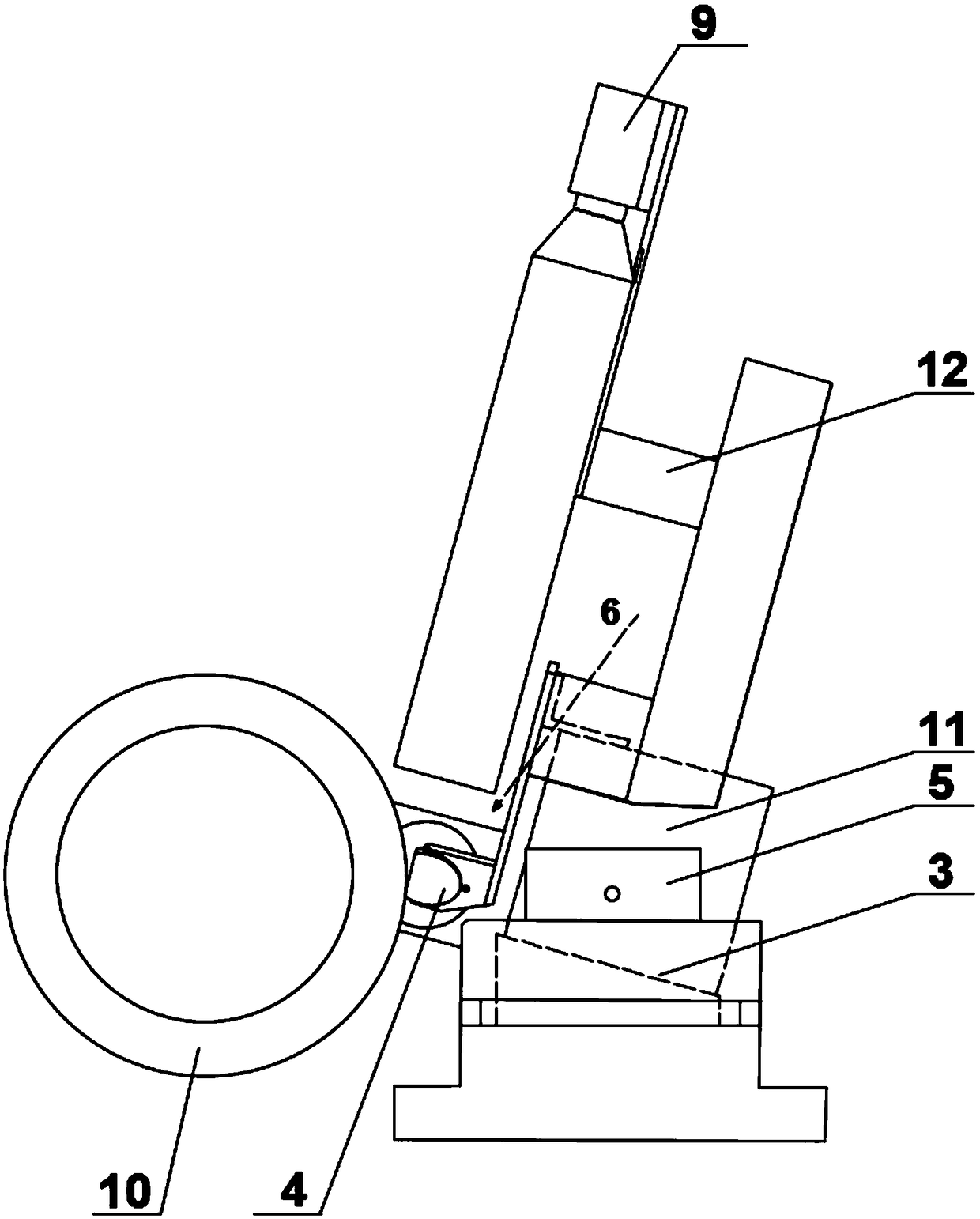
[0035] An online measurement system for high-speed cutting deformation field, the measurement system includes a signal acquisition module 1, a signal synchronization trigger module 2, a force measuring instrument 3, a mirror 4, a tool holder 5, a laser 6, a position sensor 7, an infrared camera 8, A double-frame camera 9, a coarse displacement adjustment platform 11, a fine displacement adjustme...


PUM


Abstract

The invention belongs to the field of metal machining, and discloses an online measuring system for a high-speed cutting deformation field and a method thereof. The online measuring system comprises adynamometer, an infrared camera, a dual-frame camera, a position sensor, a signal synchronous triggering module and a signal acquisition module, wherein the dynamometer is used for measuring the cutting force of a workpiece to be measured in real time; the infrared camera is used for measuring the temperature field of the workpiece to be measured in real time; the double-frame camera is used formeasuring the displacement field of the workpiece to be measured in real time; the position sensor is used for sending a measurement starting signal; after the signal synchronous triggering module receives the measurement starting signal, the signal synchronous triggering module controls the dynamometer, the infrared camera and the dual-frame camera to start measurement according to the preset time delay; and the signal acquisition module is used for acquiring results obtained by measurement, so that the online measurement of the cutting force, temperature field and displacement field of the workpiece to be measured in the high-speed cutting process is realized. Through the online measuring system and method thereof, the non-contact measurement of the transient deformation field and the temperature field under high speed and high strain is realized, the measurement process is safe and reliable, and the processing precision is guaranteed.

Description

technical field [0001] The invention belongs to the field of metal cutting, and more specifically relates to an online measurement system and method for high-speed cutting deformation field. Background technique [0002] The improvement of processing quality in cutting and the optimization of process parameters depend on the basic theoretical research on the cutting process. However, the cutting behavior is usually a large deformation at a very high strain rate in a very small area on the surface of the workpiece. This material The mechanical behavior is far from the traditional mechanical experiment situation. To explore the essence of the cutting process, under certain conditions, the workpiece material will produce a process from elastic deformation to plastic deformation (slip, twinning, grain boundary sliding, diffusive creep) to fracture (separation of chips and workpiece) under the action of external force. Therefore, the study of cutting deformation can be regarded ...

Claims


Application Information

Patent Timeline
Patent Type & Authority Applications(China)
IPC IPC(8): B23Q17/20B23Q17/24
CPCB23Q17/20B23Q17/2409Y02P70/10
Inventor 张可张小明黄涛曹畅曹乐张东丁汉
Owner HUAZHONG UNIV OF SCI & TECH
Why Eureka
Try Eureka