
Environmentally-friendly efficient recovery crusher for waste injection molded parts

A technology for injection molding parts and crushers, which is applied in the field of high-efficiency recycling crushers for waste injection molding parts for environmental protection, can solve the problems that the finished products cannot meet the factory requirements, cracking/cracking, and size out of tolerance, etc., and achieve the effect of improving the crushing effect.

Inactive Publication Date: 2019-02-15
李明军
View PDF2 Cites 19 Cited by
  • Summary
  • Abstract
  • Description
  • Claims
  • Application Information

AI Technical Summary

Problems solved by technology

[0008] Injection molded parts are prone to various problems during the production process, such as shrinkage cavity, shrinkage, unsaturated mold, burr, weld line, silver wire, spray mark, burnt, warping deformation, cracking / breaking, and size out of tolerance And other common injection molding problems, resulting in finished products that cannot meet the factory requirements. Usually people focus on mold design, molding process control, product design and plastic materials to improve, and the defective products produced are usually directly discarded, resulting in a large waste of materials.

Method used


Image

  • Environmentally-friendly efficient recovery crusher for waste injection molded parts
  • Environmentally-friendly efficient recovery crusher for waste injection molded parts
  • Environmentally-friendly efficient recovery crusher for waste injection molded parts

Examples


Embodiment 1

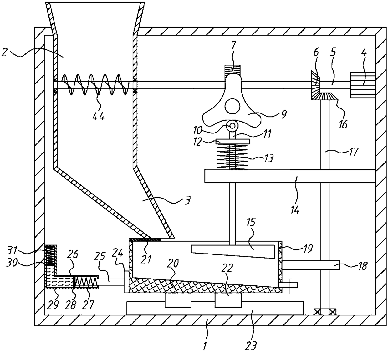
[0044] A crusher for recycling waste injection molded parts for environmental protection, including a casing 1, a feeding hopper 2, a crushing basket 19 and crushing components;

[0045] The feed hopper 2 is installed on the upper left part of the shell 1, the top of the feed hopper 2 protrudes from the top of the shell 1, and the bottom extends into the inner cavity of the shell 1 and is connected with a guide hopper 3, which is inclined downward to the right;

[0046] The middle part of the bottom plate of the housing 1 is equipped with a slide rail 23, the top of the crushing basket 19 is provided with an opening, and the bottom is fixedly connected with a slider 22, and the slider 22 is slidingly connected with the slide rail 23; the top of the left side plate of the crushing basket 19 is connected with a stop Plate 21, baffle plate 21 corresponds to the outlet at the bottom of the guide hopper 3;

[0047] The crushing assembly includes a driving motor 4, a No. 1 shaft 5, ...

Embodiment 2

[0052] A crusher for recycling waste injection molded parts for environmental protection, including a casing 1, a feeding hopper 2, a crushing basket 19 and crushing components;

[0053] The feed hopper 2 is installed on the upper left part of the shell 1, the top of the feed hopper 2 protrudes from the top of the shell 1, and the bottom extends into the inner cavity of the shell 1 and is connected with a guide hopper 3, which is inclined downward to the right;

[0054] The middle part of the bottom plate of the housing 1 is equipped with a slide rail 23, the top of the crushing basket 19 is provided with an opening, and the bottom is fixedly connected with a slider 22, and the slider 22 is slidingly connected with the slide rail 23; the top of the left side plate of the crushing basket 19 is connected with a stop Plate 21, baffle plate 21 corresponds to the outlet at the bottom of the guide hopper 3;

[0055] The crushing assembly includes a driving motor 4, a No. 1 shaft 5, ...

Embodiment 3

[0060] A crusher for recycling waste injection molded parts for environmental protection, including a casing 1, a feeding hopper 2, a crushing basket 19 and crushing components;

[0061] The feed hopper 2 is installed on the upper left part of the shell 1, the top of the feed hopper 2 protrudes from the top of the shell 1, and the bottom extends into the inner cavity of the shell 1 and is connected with a guide hopper 3, which is inclined downward to the right;

[0062] The middle part of the bottom plate of the housing 1 is equipped with a slide rail 23, the top of the crushing basket 19 is provided with an opening, and the bottom is fixedly connected with a slider 22, and the slider 22 is slidingly connected with the slide rail 23; the top of the left side plate of the crushing basket 19 is connected with a stop Plate 21, baffle plate 21 corresponds to the outlet at the bottom of the guide hopper 3;

[0063] The crushing assembly includes a driving motor 4, a No. 1 shaft 5, ...


PUM


Abstract

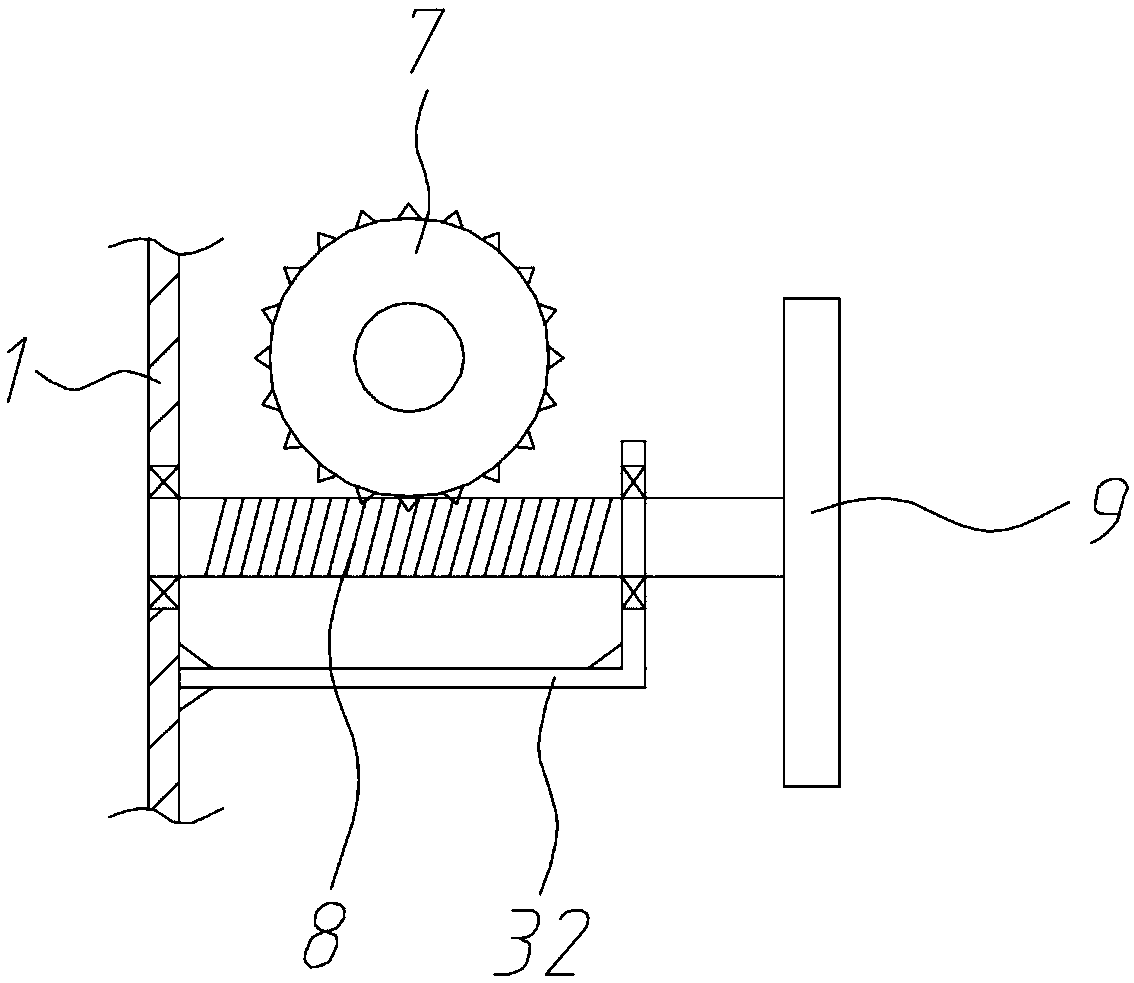
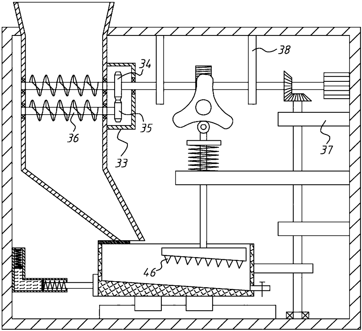
The invention relates to the technical field of waste injection molded part recovery, in particular to an environmentally-friendly efficient recovery crusher for waste injection molded parts. A firstshaft is driven by a drive motor to rotate to exert multiple effects that firstly, a second shaft is driven by transmission of bevel gears to rotate, so that a disc-shaped cam acts on a crushing basket, and cooperates with a piston barrel at the right side to make the crushing basket do reciprocating motion along a sliding rail, and therefore, the action region of a crushing tip is changed; secondly, a triangular cam is driven by a worm gear and a worm to rotate, and through functions of a roller and a first spring, the crushing tip is driven to vertically move to crush the injection molded parts in the crushing basket; thirdly, a spiral auger is also arranged on the inner section, located in a feed hopper, of the first shaft, and the waste injection molded parts firstly undergo the crushing action of the spiral auger when being put into the feed hopper, and then, fall into the crushing basket and are crushed; and fourthly, the outlet of a guide hopper is blocked by a baffle when the baffle is in an initial state, and during reciprocating motion of the crushing basket, the baffle moves along with the crushing basket to realize intermittent discharging.

Description

technical field [0001] The invention relates to the technical field of recycling waste injection molded parts, in particular to an environmentally friendly crusher for efficiently recycling waste injection molded parts. Background technique [0002] Injection molding is a method of producing shapes for industrial products. Products usually use rubber injection molding and plastic injection molding. Injection molding can also be divided into injection molding molding method and die casting method. [0003] Injection molding machine (referred to as injection machine or injection molding machine) is the main molding equipment for making thermoplastic or thermosetting materials into various shapes of plastic products using plastic molding molds. Injection molding is realized through injection molding machines and molds. An injection molding machine has two basic components: the injection unit and the clamping unit for melting and feeding the plastic into the mold. On the one ...

Claims


Application Information

Patent Timeline
Patent Type & Authority Applications(China)
IPC IPC(8): B29B17/04B29C45/17B02C19/22B02C1/00B02C23/00
CPCB02C1/00B02C19/22B02C23/00B29B17/04B29C45/17Y02W30/52Y02W30/62
Inventor 李明军
Owner 李明军
Learn More