A cavity structure and its preparation method

A cavity and cavity preparation technology, applied in the field of composite materials, can solve the problems of low reliability and difficult manufacturing, and achieve the effects of good adaptability, simple molding tooling, and reduced manufacturing difficulty

Active Publication Date: 2020-11-13
AEROSPACE INST OF ADVANCED MATERIALS & PROCESSING TECH
View PDF7 Cites 0 Cited by
  • Summary
  • Abstract
  • Description
  • Claims
  • Application Information

AI Technical Summary

Problems solved by technology

[0006] The purpose of the present invention is to overcome the deficiencies of the prior art, and provide a composite material molding method that solves the difficulty in overall manufacturing and low reliability of a complex special-shaped variable-section thin-walled cavity structure such as a serpentine stealth air inlet, so as to ensure this The structure has the structural rigidity, strength and reliability that meet the design and use requirements

Method used


Image

  • A cavity structure and its preparation method
  • A cavity structure and its preparation method
  • A cavity structure and its preparation method

Examples


Embodiment 1

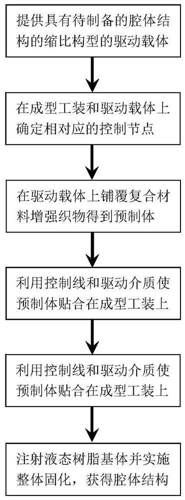
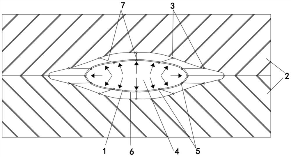
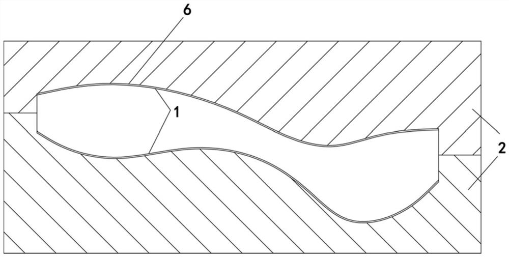
[0058] In this embodiment, a thin-wall cavity structure with special-shaped variable cross-section made of composite material is made. figure 2 As shown, the longitudinal section is as image 3 As shown, it includes driving carrier 1, forming tooling 2, driving carrier control node on the forming tooling (i.e. forming tooling control node) 3, flowing driving medium 4, control node on the driving carrier (i.e. driving carrier control node) 5, cavity Body structure prefabricated body 6, control line 7, the maximum length of the envelope of the cavity structure is 1200mm, the maximum width of the envelope is 460mm, the maximum height of the envelope is 220mm, and the wall thickness is 2.4mm. Layup is [(0 / 90) f / (45 / 0 / -45 / 90) 2 ] s ,((0 / 90) f Indicates plain weave fabric, () 2 Indicates that the layers in parentheses are cycled twice, [] s Indicates that the layers in the square brackets are laid first, and on this basis, the layers symmetrical to the above layers are laid....

Embodiment 2

[0074] The method is basically the same as that of Example 1, except that the driving carrier is made of aramid non-woven material with a breaking elongation of 400%.

Embodiment 3

[0076]The method is basically the same as in Example 1, except that the control thread is a glass fiber thread.


PUM

PropertyMeasurementUnit
lengthaaaaaaaaaa
widthaaaaaaaaaa
heightaaaaaaaaaa

Abstract

The invention relates to a cavity structure and a preparation method for the same. The method comprises the steps that a drive carrier with a geometrical similarity is provided; corresponding controlnodes are disposed on a formed fixture and the drive carrier respectively; a composite reinforced fabric is paved and fixed on the drive carrier to form a prefabricated body; the prefabricated body isadhered on the formed fixture by a fluid drive medium; and a liquid state matrix is injected and solidified, so the cavity structure can be obtained. The invention also provides the cavity structuremade with the method. The method provided by the invention is extensively applicable and especially applicable to complicated thin-wall cavity structures with abrupt cross-section changes and great changes of main axis curvatures of cavities; problems in traditional technologies such as difficulty in paving and demoulding can be solved; the formed fixture is simple and does not have many requirements for equipment, and the duration is short; and the fabricated cavity structure has a good appearance and high accuracy, is free of layering and loosening and is highly overall and reliable.

Description

technical field [0001] The invention relates to a cavity structure and a preparation method thereof, in particular to a composite material special-shaped variable-section thin-wall cavity and an integral molding preparation method thereof, belonging to the technical field of composite materials. Background technique [0002] Considering functional factors such as structural electromagnetic wave stealth performance and aerodynamic performance, both the stealth drone and the stealth aircraft air intake adopt a thin-walled hollow structure with complex curved surface features. By increasing the complexity of the structure shape, it meets Requirements for low RCS and low drag coefficient indicators, such as the snake-shaped inlet of the "Sharp Sword" stealth drone and the general-purpose stealth subsonic cruise missile. The complexity of the shape features and the particularity of the thin-walled hollow structure make it difficult to realize the manufacturing of such structures ...

Claims


Application Information

Patent Timeline
Patent Type & Authority Patents(China)
IPC IPC(8): B29C70/36
CPCB29C70/36
Inventor 张涛许亚洪陈磊李卓达夏雅男辛颖
Owner AEROSPACE INST OF ADVANCED MATERIALS & PROCESSING TECH
Why Eureka
Try Eureka