Pneumatic-electric braking system and Pneumatic-electric conversion and control method of freight train

A braking system, air-electric technology, applied in the direction of brakes, brake components, brake transmission devices, etc., can solve the problems of brake control restrictions, low truck capacity, high maintenance and use costs, etc., to ensure compatibility , to ensure the effect of safety

Inactive Publication Date: 2019-02-15
EAST CHINA NORMAL UNIV
View PDF6 Cites 1 Cited by
  • Summary
  • Abstract
  • Description
  • Claims
  • Application Information

AI Technical Summary

Problems solved by technology

[0003] In the past, railway freight trains have always used the air brake system, but in today's express freight trains, the air brake system has shown its shortcomings: longer braking distance, insensitive adjustment of empty freight, lack of vehicle anti-skid, etc. Equipment, as well as the excessive longitudinal impulse between vehicles caused by the inconsistency of braking between vehicles, in addition, it will cause excessive wear or premature damage of wheels, brake shoes, couplers, drawbars, etc., which will eventually lead to higher maintenance and repair of vehicles. Lower cost of use and lower truck capacity
These all show that the traditional air brake system is difficult to use on express freight trains
[0004] Existing mechanical control is difficult to achieve the anti-skid of fast freight trains under high-power braking, the adjustment of braking force when there is a huge difference between the load of empty and heavy vehicles, and the requirements for improving the braking performance of mixed trains and long trains. Therefore, it is urgent electronic control is required
However, at present, most freight trains do not have their own power supply, and it is difficult to implement cable power supply based on fixed marshalling, which cannot provide the required low-power electric energy for the on-board control system, which severely limits the development of brake control technology.

Method used


Image

  • Pneumatic-electric braking system and Pneumatic-electric conversion and control method of freight train
  • Pneumatic-electric braking system and Pneumatic-electric conversion and control method of freight train
  • Pneumatic-electric braking system and Pneumatic-electric conversion and control method of freight train

Examples


Embodiment 1

[0023] A control method based on aerodynamic power generation of freight trains mainly includes the following steps:

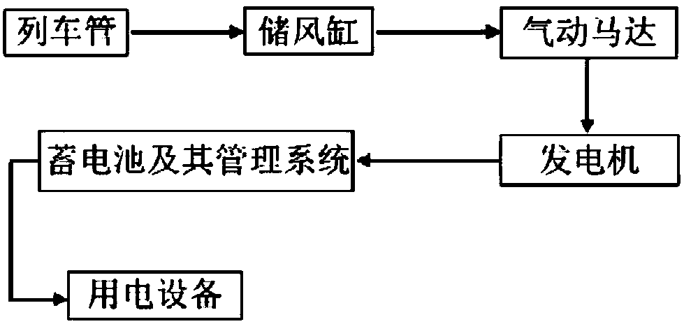
[0024] 1) The main components of the pneumatic power generation device

[0025] refer to figure 1 , The pneumatic power generation device mainly includes: train tube, air storage cylinder, air motor, generator, battery and its battery management system. Among them, the air storage cylinder receives the pressure air of the train pipeline through the one-way air circuit; the air motor is connected to the pressure air pressure air storage cylinder, receives the air pressure and converts it into mechanical power output; the power is input into the generator through the coupling for power generation ;Finally, after passing through the battery management system, it is input into the battery to convert the air pressure into electric energy and supply power for the vehicle control equipment. In the present invention, the generator may be a small generator.

[0026]...


PUM


Abstract

The invention relates to an air pressure braking system. The air pressure braking system comprises a controller, an air compressor, an air supply pipe, a pressure/air power generation device, a pneumatic motor, a pneumatic power generation device, a storage battery and a storage battery management system, wherein the controller comprises a micro-processing control unit and a control electromagnetic valve. The air pressure braking system is mainly applied to a pneumatic-electric conversion and control method of a freight train. According to the pneumatic-electric conversion and control method of the freight train, an air braking signal of the air pressure braking system is converted into a voltage signal; energy is stored by using the storage battery management system; power is supplied toa control device by using an energy storage system; and therefore, the braking of the freight train is accurately controlled.

Description

technical field [0001] The present invention relates to the field of aerodynamic power generation control of freight trains, to the field of electronically controlled air brakes, in particular to an air-electric brake system and an air-to-electricity conversion and control method for freight trains, and in particular to using the original pressure of an air supply pipe for power supply , applied to train electronically controlled air brakes. Background technique [0002] Railway freight is developing in the direction of fast freight. In order to ensure the safety and efficiency of railway transportation, the requirements for vehicle braking systems are also increasing. [0003] In the past, railway freight trains have always used the air brake system, but in today's express freight trains, the air brake system has shown its shortcomings: longer braking distance, insensitive adjustment of empty freight, lack of vehicle anti-skid, etc. Equipment, as well as the excessive long...

Claims


Application Information

Patent Timeline
Patent Type & Authority Applications(China)
IPC IPC(8): B60T13/26B60T17/00F03D9/11F03D9/25F03D9/32
CPCB60T13/26B60T17/00F03D9/11F03D9/25F03D9/32Y02E10/72Y02E10/728Y02E70/30
Inventor 万嘉昕栾天李致健李晓敏邱崧
Owner EAST CHINA NORMAL UNIV
Why Eureka
Try Eureka