Efficient oil-water phase separation device

A high-efficiency oil and water technology, applied in the direction of grease/oily substance/float removal device, liquid separation, separation method, etc., can solve the problem of low separation efficiency, avoid liquid flow turbulence, improve oil-water separation effect and separation Efficiency, the effect of slowing down the flow rate

Pending Publication Date: 2019-02-15
宁夏睿源精细化工有限公司
View PDF5 Cites 0 Cited by
  • Summary
  • Abstract
  • Description
  • Claims
  • Application Information

AI Technical Summary

Problems solved by technology

[0004] The purpose of this application is to provide a high-efficiency oil-water phase device to solve the problem of low separation efficiency of existing oil-water phase devices

Method used


Image

  • Efficient oil-water phase separation device
  • Efficient oil-water phase separation device

Examples


Embodiment Construction

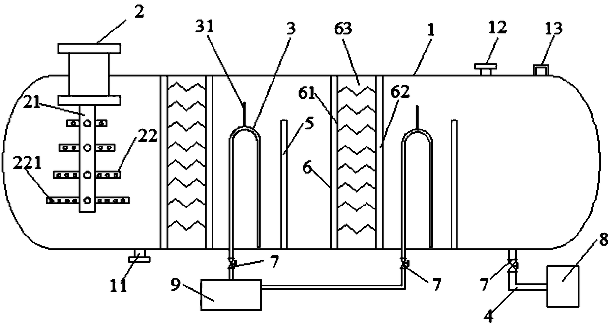
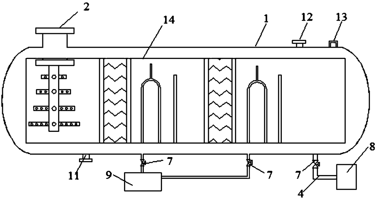
[0024] refer to figure 1 , the embodiment of the present application provides a high-efficiency oil-water phase device, including: a tank body 1, an oil-water feed pipe 2, a water outlet pipe 3, an oil outlet pipe 4, several partitions 5 and several packing chambers 6;

[0025] The oil-water feed pipe 2, the water outlet pipe 3 and the oil outlet pipe 4 are respectively communicated with the tank body 1, and the oil outlet pipe 4 is arranged at an end of the tank body 1 away from the oil-water feed pipe 2 ;

[0026] The filler chamber 6 and the partition plate 5 are arranged at intervals inside the tank body 1, the filler chamber 6 is arranged between the partition plate 5 and the oil-water feed pipe 2, and the water outlet pipe 3 Provided between the packing chamber 6 and the partition 5, the height of the partition 5 is smaller than the inner cavity height of the tank body 1;

[0027] The oil-water feed pipe 2 includes a feed pipe body 21 and an extension pipe 22 communica...


PUM


Abstract

The invention discloses a efficient oil-water phase separation device which comprises a tank body, an oil-water inlet pipe, a water outlet pipe, an oil outlet pipe, a plurality of baffles and a plurality of filling cavities, wherein the oil-water inlet pipe, the water outlet pipe and the oil outlet pipe are respectively communicated with the tank body; the filling cavities and the baffles are disposed in the tank body in a spacing manner; the height of each of the baffles is less than that of an inner cavity of the tank body; the oil-water inlet pipe comprises a material inlet pipe body and anextending pipe; a plurality of material outlet holes are formed in the extending pipe; the filling cavities comprise filler pressing rings, fixing plates and coalesced fillers; the water outlet pipeis of an inverted U shape; the top height of the water outlet pipe is less than the heights of the baffles; the water outlet pipe is provided with a water outlet pipe vent; the height of the water outlet pipe vent is greater than the heights of the baffles; flow regulating valves are arranged on the water outlet pipe and the oil outlet pipe. According to the efficient oil-water phase separation device, an oil-water mixture passes through the plurality of filling cavities and partitions to realize continuous separation of oil and water, thereby improving the oil-water separation effect and separation efficiency. The extending pipe on the oil-water inlet pipe can reduce the flow rate of the oil-water mixture, so as to effectively avoid the turbulence of the liquid flow and improve the coalescencing effect.

Description

technical field [0001] The present application relates to the technical field of oil-water treatment, in particular to a high-efficiency oil-water phase device. Background technique [0002] Oily wastewater mainly comes from petroleum, petrochemical, steel, coking, gas generation stations, mechanical processing and other industrial sectors. If oily wastewater is not recycled, it will cause waste; if it is discharged into rivers, lakes or bays, it will pollute water bodies and affect aquatic life. Biological survival; used for agricultural irrigation, it will block the soil gap and hinder the growth of crops. The current overflow stratification method occupies a large area of ​​equipment, the stratification effect is not good, and the entrainment is too much. The defects are as follows: waste of oil phase; pollution of water phase; Secondary pollution may cause poor product (PCB) processing quality; high COD in the water phase will increase the pressure of environmental prot...

Claims


Application Information

Patent Timeline
IPC IPC(8): C02F1/40B01D17/025B01D21/02B01D17/02
CPCB01D17/02B01D17/0208B01D17/0211B01D21/02C02F1/40C02F2001/007
Inventor 张景辉张雷王亚栋王强
Owner 宁夏睿源精细化工有限公司
Why Eureka
Try Eureka