Three-stage oil-water separator

A technology of oil-water separator and sub-assembly, which is applied in the direction of machines/engines, engine components, liquid fuel feeders, etc., can solve the problems of oil-water separation efficiency decline, achieve thorough filtration of water particles and impurities, compact structure, and reasonable layout Effect

Pending Publication Date: 2019-02-15
广西华原过滤系统股份有限公司
View PDF0 Cites 4 Cited by
  • Summary
  • Abstract
  • Description
  • Claims
  • Application Information

AI Technical Summary

Problems solved by technology

[0004] The purpose of the present invention is to overcome the shortcomings of the above-mentioned existing oil-water separator that can only filter large-particle water droplets and the oil-water separation efficiency decreases after a period

Method used


Image

  • Three-stage oil-water separator
  • Three-stage oil-water separator
  • Three-stage oil-water separator

Examples


Embodiment Construction

[0025] The specific embodiments of the present invention will be described in detail below in conjunction with the accompanying drawings, but it should be understood that the protection scope of the present invention is not limited by the specific embodiments.

[0026] Unless expressly stated otherwise, throughout the specification and claims, the term "comprise" or variations thereof such as "includes" or "includes" and the like will be understood to include the stated elements or constituents, and not Other elements or other components are not excluded.

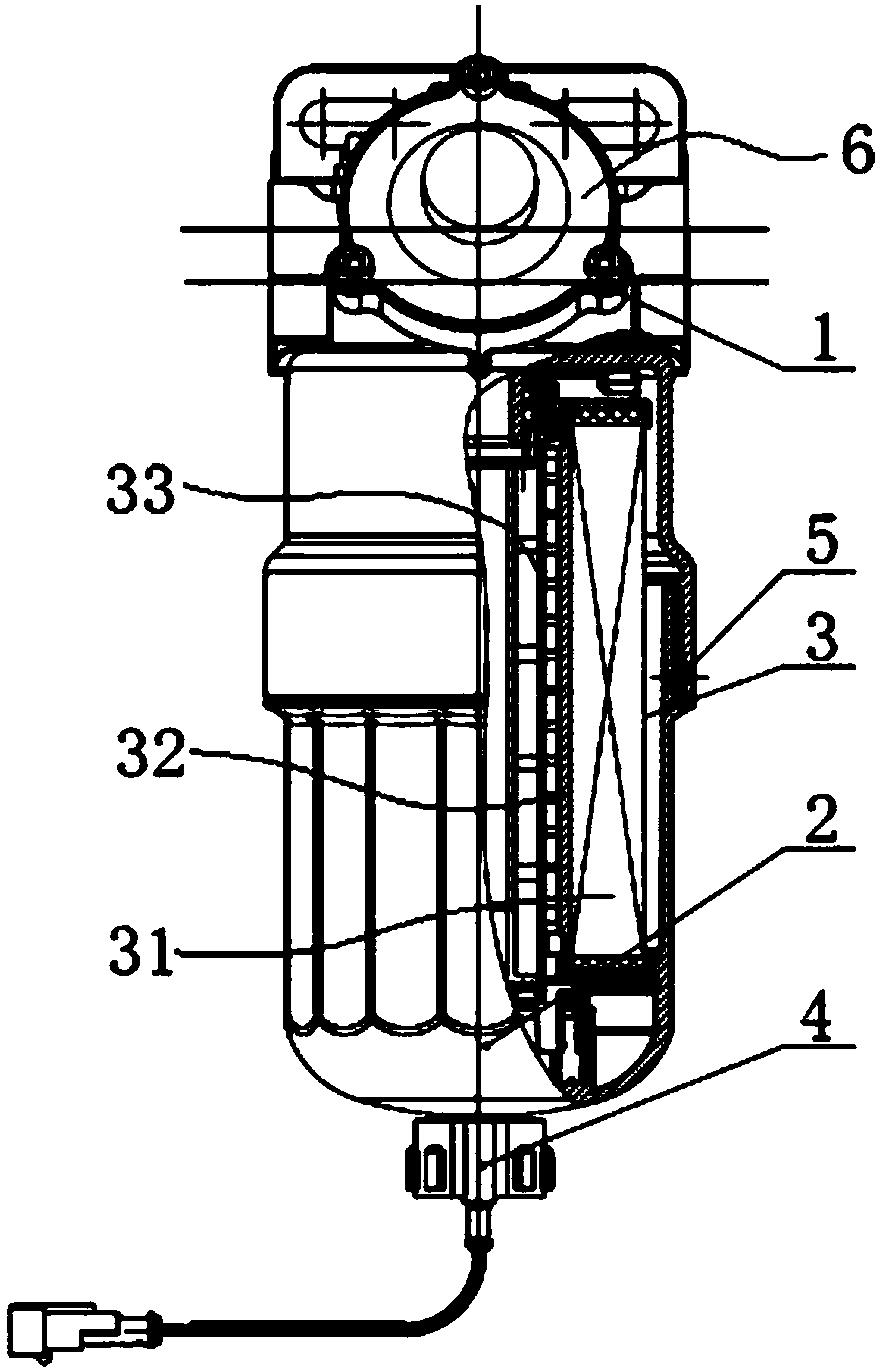
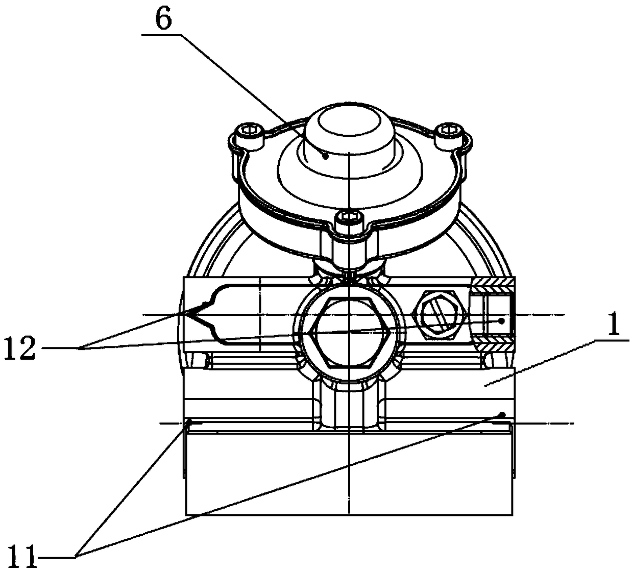
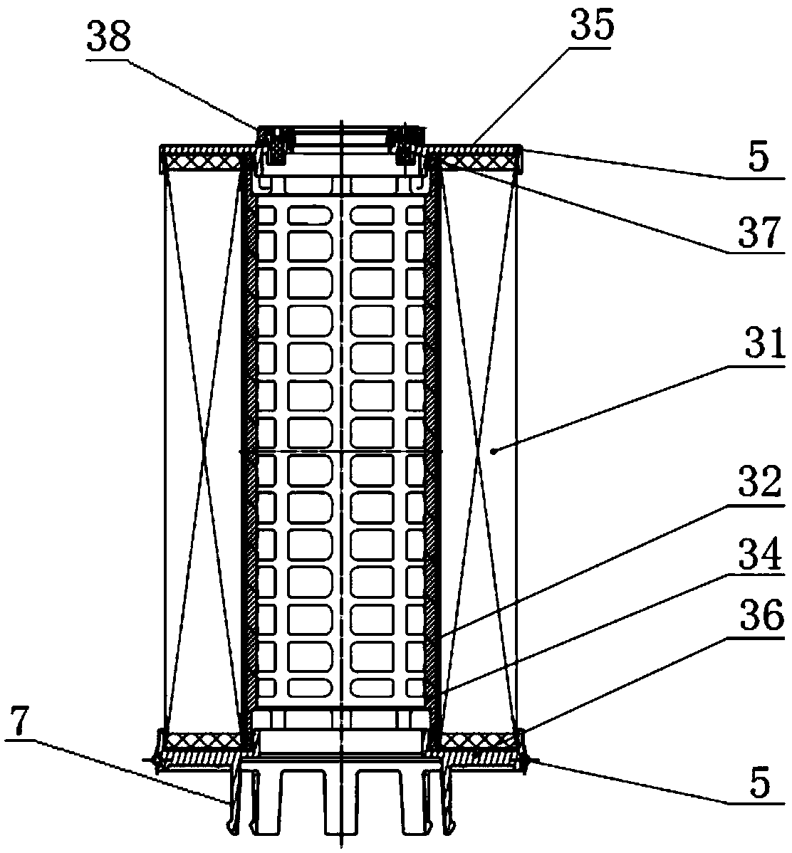
[0027] Such as Figure 1 to Figure 5 As shown, the present invention provides a three-stage oil-water separator, which includes a filter seat subassembly 1 , a housing 2 and a filter element assembly 3 . Such as figure 1 As shown, the lower end of the filter seat subassembly 1 is connected to the upper end of the shell 2, and the filter element assembly 3 is arranged in the inner cavity formed after the filter seat subass...


PUM


Abstract

The invention discloses a three-stage oil-water separator. The three-stage oil-water separator comprises a filter seat sub-assembly, a shell and a filter element assembly, wherein the lower end of thefilter seat sub-assembly is connected with the upper end of the shell, and the filter element assembly is disposed in an inner cavity formed by connecting the filter seat sub-assembly with the shell;the filter element assembly includes a first filter layer, a second filter layer and a third filter layer which are distributed layer by layer from outside to inside; and the first filter layer is folded to be in a folded cylindrical shape by filter paper, and the second filter layer and the third filter layer are wound to be in a cylindrical shape by filter paper. The three-stage oil-water separator has reasonable arrangement and a compact structure, and realizes three-stage filtration through three filter layers, and thus, small particle water droplets can be effectively filtered, the three-stage oil-water separator is not easily affected by solid particles, and it is effectively ensured that the oil-water separator has higher oil-water separation efficiency in the use process.

Description

technical field [0001] The present invention relates to the technical field of fuel filter systems, and more specifically relates to a three-stage oil-water separator. Background technique [0002] In the current fuel oil filtration system, it is necessary to filter and remove the solid impurities in the fuel, and also need to filter and remove the water impurities in the fuel. Compared with the solid impurities, the damage caused by the water impurities in the fuel is more serious, and the water impurities will corrode Engine components can breed microorganisms and bacteria, and corrosive substances in the water can also cause damage to components and accelerate fuel oxidation. At present, the oil-water separator for filtering fuel oil mainly adopts a single-stage, barrier-type filtration method. In such a structure, hydrophobic materials are mainly used as filter materials, so that water particles are blocked in the filter by means of barrier-type separation of water parti...

Claims


Application Information

Patent Timeline
IPC IPC(8): F02M37/34F02M37/24F02M37/54
CPCF02M37/22
Inventor 黄开冰庞武明罗展
Owner 广西华原过滤系统股份有限公司
Why Eureka
Try Eureka