Cooling fin and cascaded caulking groove radiator

A heat dissipation fin and heat sink technology, applied in indirect heat exchangers, heat exchange equipment, lighting and heating equipment, etc., can solve the small contact area between the base and the phase change chamber, and reduce the heat dissipation effect of the phase change chamber , large contact thermal resistance, etc., to achieve the effect of convenient installation and operation, easy processing and manufacturing, and small transfer thermal resistance

Pending Publication Date: 2019-02-15
常州恒创热管理有限公司
View PDF6 Cites 14 Cited by
  • Summary
  • Abstract
  • Description
  • Claims
  • Application Information

AI Technical Summary

Problems solved by technology

[0007] In order to solve the problem of poor manufacturability and low production efficiency of the cog process between the vapor chamber and the base in the prior art, as well as the small contact area between the base and the phase change chamber and large contact thermal resistance, which reduces the heat dissipation of the phase change chamber Effect of the problem, the present invention provides a cooling fin and cascaded slot radiator

Method used


Image

  • Cooling fin and cascaded caulking groove radiator
  • Cooling fin and cascaded caulking groove radiator
  • Cooling fin and cascaded caulking groove radiator

Examples


Embodiment 1

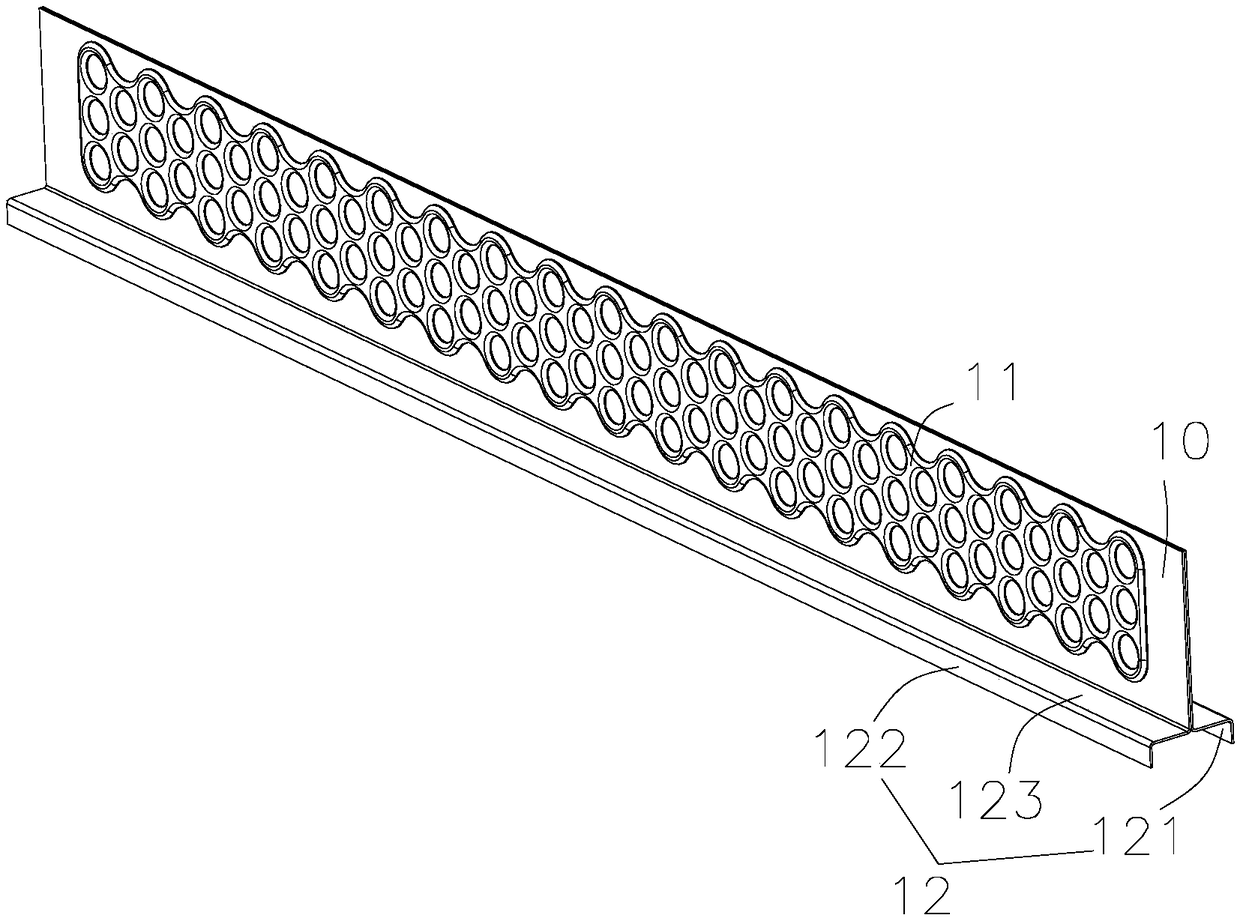
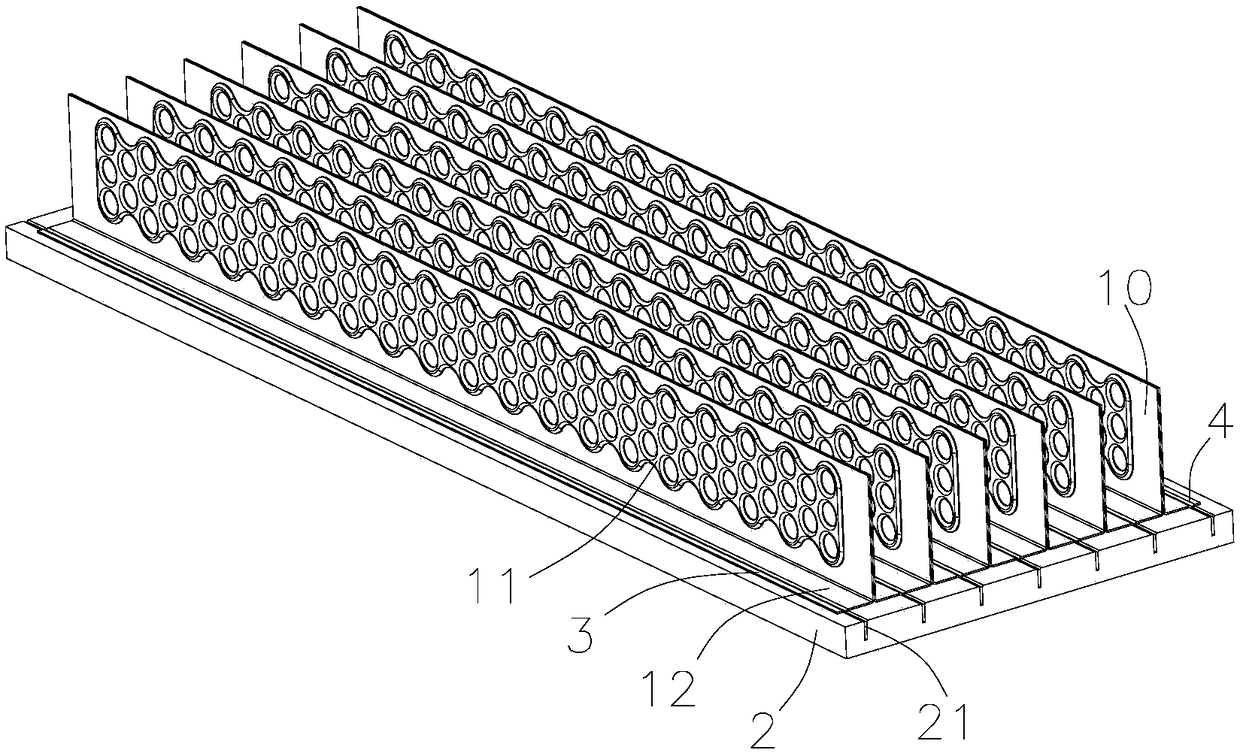
[0037] Such as Figure 2~4 As shown, a heat dissipation fin includes a fin body 10 and a bent portion 12, one side of the fin body 10 has the bent portion 12, and the cross section of the bent portion 12 is n-shaped, The bending part 12 includes a first bending section 121, a second bending section 122 and a connecting section 123 connecting the first bending section 121 and the second bending section 122, the first bending section 121 and the second bending section 121 The two bending sections 122 are separated from each other, and the first bending section 121 and the second bending section 122 are parallel to each other. Specifically, the fins are compositely formed by two substrates, and it is in a plate structure, and a closed hollow cavity 11 is arranged between the two substrates, and the hollow cavity 11 is filled with a phase change working fluid. And in a negative pressure state, this kind of fin is also called a flat heat pipe, which conducts heat through the phase...

Embodiment 2

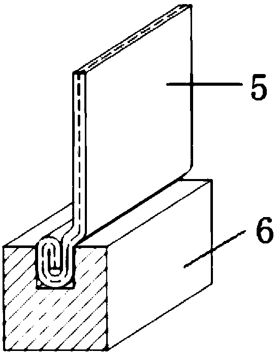
[0050] In this embodiment, the difference between a cascaded slot radiator and Embodiment 1 is that the width of the first installation groove 21 among the several installation grooves 21 is the same as the thickness of the first bent section 121. matching, the width of the last mounting groove 21 matches the thickness of the second bent section 122; the first bent section 121 of the first fin in the plurality of fins is interference inserted into the second In one of the installation grooves 21 , the second bent section 122 of the last fin is interference inserted into the last installation groove 21 , and the first slotting piece 3 and the second slotting piece 4 are not needed.

Embodiment 3

[0052] Such as Figure 5-7 As shown, in this embodiment, the difference between a heat dissipation fin and Embodiment 1 is that the first bending section 121 and the second bending section 122 are located on the same side of the fin body 10, and the first The bending section 121 is arranged close to the fin body 10, and the first bending section 121 and the second bending section 122 are formed by bending two substrates to one side of the fin body 10 at the same time. Separate the sides of the two substrates. For flat plate heat pipe fins filled with phase-change working fluid, it is difficult to realize the processing technology of bending two substrates to form separate bending parts 12, but in this embodiment, the sides of the fins are directly bent, which is convenient for processing and manufacturing, and Wide range of applications.

[0053] Such as Image 6 with 7 As shown, in this embodiment, the difference between a cascaded slot radiator and Embodiment 1 is that i...


PUM


Abstract

The invention belongs to the technical field of radiators, and particularly relates to a cooling fin and a cascaded caulking groove radiator. The cooling fin comprises a fin body and a bent part. At least one side edge of the fin body is provided with the bent part. The bent part comprises a first bent section, a second bent section, and a connecting section for connecting the first bent section with the second bent section. The first bent section and the second bent section are mutually separated, and the first bent section and the second bent section are mutually parallel. The cooling fin and the cascaded caulking groove radiator have the beneficial effects that according to the cascaded caulking groove radiator, as a first bent section of one fin is arranged in a mounting groove, when asecond bent section of the other fin is extruded into the same mounting groove, the second bent section achieves the effect of a wedge, the second bent section, the inner wall of the mounting grooveand the first bent section are extruded tightly, the mounting operation is convenient, and assembly is reliable and not likely to loosen; and according to the cascaded caulking groove radiator, the contact area of the fins and a base is large, transfer heat resistance is small, and therefore better cooling performance is achieved.

Description

technical field [0001] The invention belongs to the technical field of heat sinks, in particular to a heat dissipation fin and cascaded embedded groove heat sink. Background technique [0002] With the rapid development of power electronic equipment and devices towards miniaturization, integration, and high efficiency, device performance and heat dissipation continue to increase, resulting in uneven distribution of heat flux density, extremely high local heat flux density, and heat accumulation in local areas. The problem of local overheating. These problems pose new challenges to the thermal design of power electronic equipment, requiring thermal management systems to meet the requirements of high performance, high compactness, high reliability, and high flexibility. [0003] The heat pipe is a highly efficient heat transfer element with high heat transfer efficiency and heat flux. At present, tubular micro-heat pipes have been widely used in equipment thermal management ...

Claims


Application Information

Patent Timeline
Patent Type & Authority Applications(China)
IPC IPC(8): F28F3/00F28D15/02
CPCF28D15/02F28F3/00
Inventor 黄晓峰徐栋
Owner 常州恒创热管理有限公司
Why Eureka
Try Eureka