Supercharge Your Innovation With Domain-Expert AI Agents!

Rotatable spray gun and hot melt glue spray gun

A technology of rotating spray gun and hot melt adhesive, which is applied to spray devices, liquid spray devices, spray devices with movable outlets, etc. problem, to achieve the effect of compact structure, stable temperature and small thermal expansion coefficient

Pending Publication Date: 2019-02-19
东莞裕鸿智能科技有限公司
View PDF15 Cites 2 Cited by
  • Summary
  • Abstract
  • Description
  • Claims
  • Application Information

AI Technical Summary

Problems solved by technology

[0002] In the traditional structure, the spray gun body is connected with the thermal fluid heating insulation block. When the needle valve piston rises, the fluid is directly sprayed vertically from the channel in the lower cover of the spray gun, or an L-shaped nozzle is installed to make the fluid fixed toward a Side spraying, when it is necessary to spray fluid on the inner or outer periphery of a square box or a round tank, it is necessary to insulate the entire spray gun body together with the heating part and the fluid heat supply pipe, solenoid valve, solenoid valve control line, The air pipes rotate together. Due to the limitation of the volume and self-weight of various pipelines and spray guns, the traditional spraying structure cannot rotate and spray in multiple circular cycles. At the same time, it is difficult to rotate the entire structure in a small radius space, resulting in poor spraying effect. Unable to meet market demand

Method used


Image

  • Rotatable spray gun and hot melt glue spray gun
  • Rotatable spray gun and hot melt glue spray gun
  • Rotatable spray gun and hot melt glue spray gun

Examples


Embodiment 1

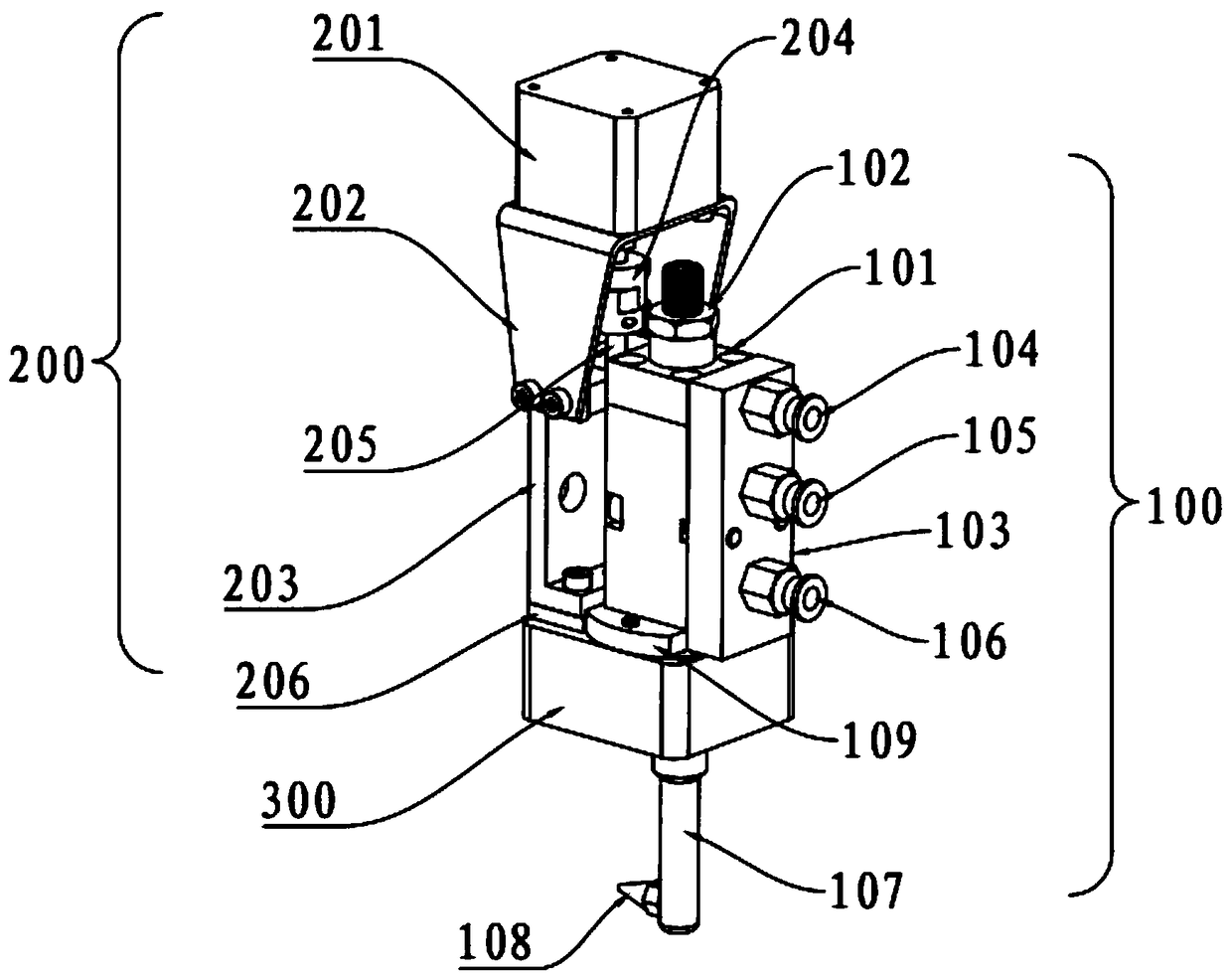
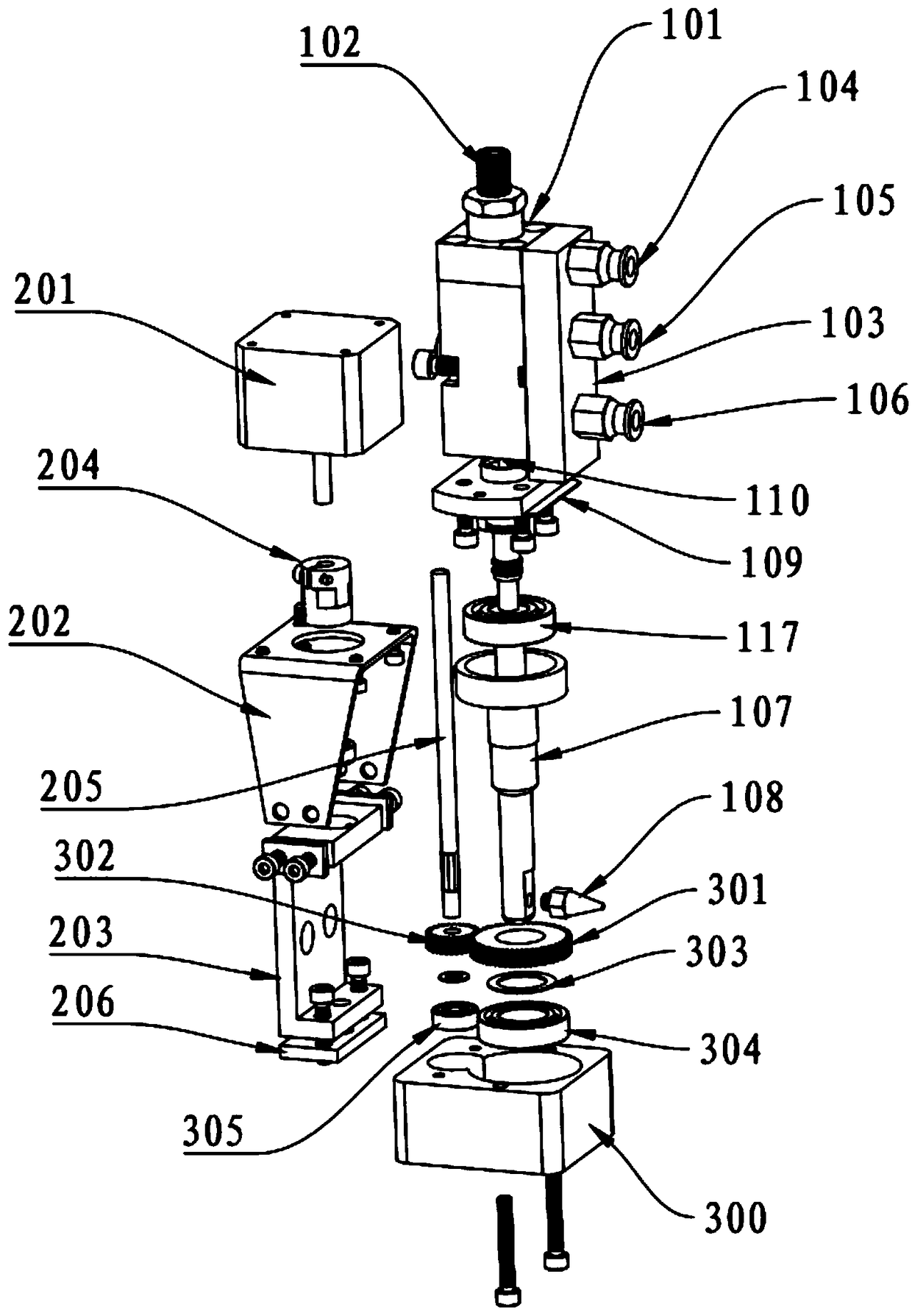
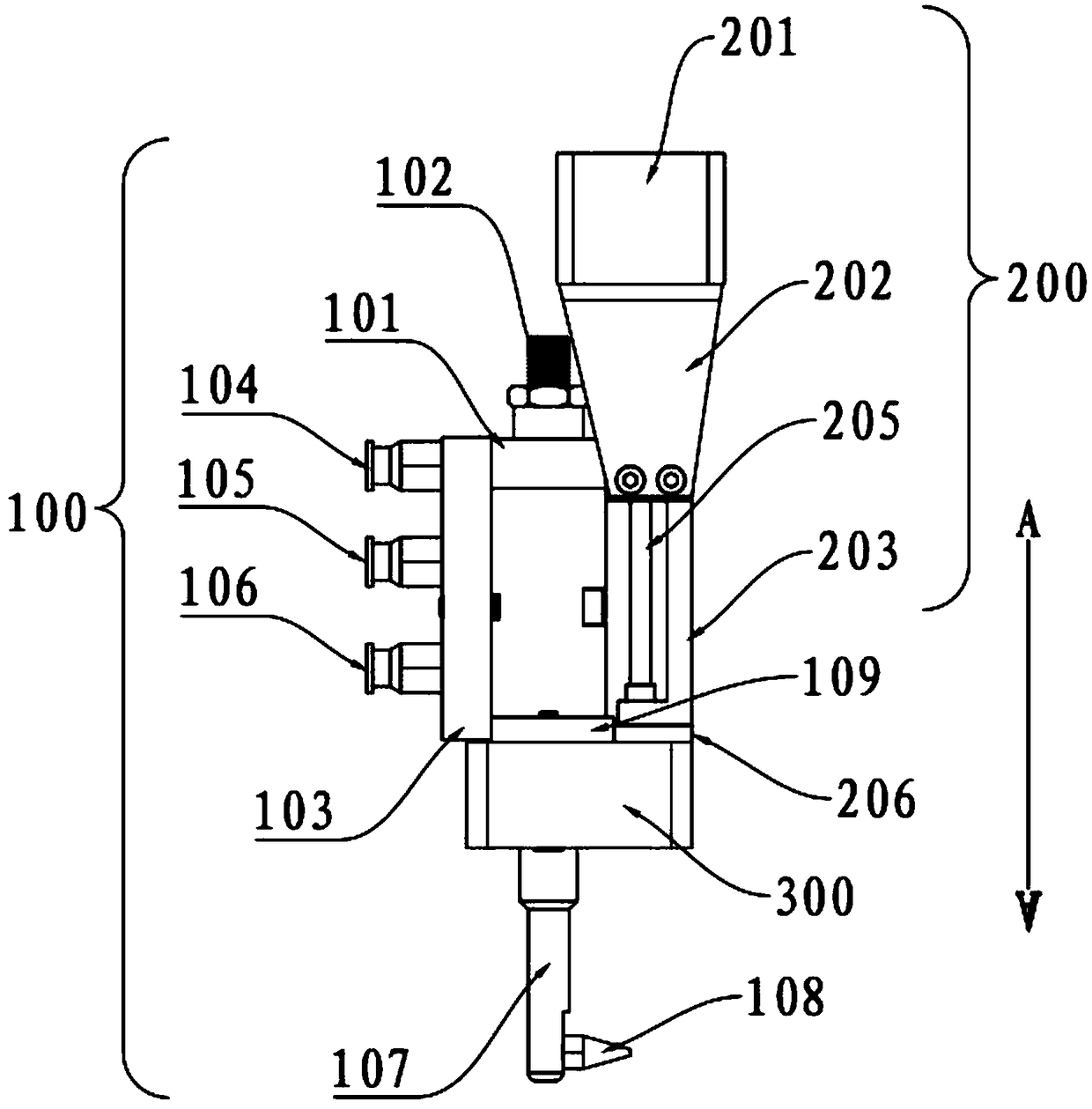
[0040] like figure 1 , figure 2 , image 3 , Figure 4 , Figure 5 and Image 6 As shown, a rotatable spray gun includes a mounting base 300, a glue spraying device 100 and a driving device 200 that drives the glue spraying device 100 to rotate;

[0041] The glue spraying device 100 includes a spray gun body 101 with a liquid glue accommodation chamber inside, and the spray gun body 101 is fixed on the mounting seat 300 via a base 109;

[0042] One side of the spray gun body 101 is provided with a first air inlet 115, a second air inlet 116 and a liquid inlet 111 communicating with the accommodating chamber;

[0043] The spray gun body 101 is provided with an adjusting screw 102, the chamber of the spray gun body 101 is provided with a piston 114 and a thimble 110, one end of the thimble 110 is fixedly connected to the piston 114, and the thimble 110 The other end is arranged on the liquid outlet of the chamber of the spray gun body 101;

[0044] An elastic body 113 is...

Embodiment 2

[0057] like Figure 7 , Figure 8 and Figure 9 As shown, a hot melt adhesive spray gun also includes a thermal insulation heating device 400 fixed on one side of the spray gun body 101. The thermal insulation heating device 400 includes a solenoid valve 402 and a heating insulation block 404. The solenoid valve 402 The air supply pipe 403 is fixed on the heating insulation block 404, the solenoid valve 402 is fixedly provided with an air supply joint 401 communicating with the air supply pipe 403, and one end of the air supply pipe 403 passes through the heating insulation block. The block 404 is correspondingly connected to the first air inlet 115 and the second air inlet 116. The heating and insulating block 404 is also provided with a liquid inlet 405 and a heating pipe installation hole 406. The heating and insulating block 404 is provided with a fluid chamber 407 communicating with the liquid inlet 405 , and the fluid chamber 407 is correspondingly connected to the liq...


PUM


Abstract

The invention relates to the technical field of glue spraying, in particular to a rotatable spray gun and a hot melt glue spray gun. The rotatable spray gun comprises a mounting seat, a glue sprayingdevice and a driving device which drives the glue spraying device to rotate. The glue spraying device comprises a spray gun body internally provided with a liquid glue accommodating cavity, and the spray gun body is fixedly arranged on the mounting seat through a base. The driving device comprises a motor, a motor seat and a driving shaft, the motor is fixedly arranged on the motor seat, the motorseat is fixedly arranged on the mounting seat through a driving shaft seat, one end of the driving shaft is connected to an output shaft of the motor, and the other end of the driving shaft is connected to a second gear. The motor drives the driving shaft to drive a first gear to enable a sleeve to rotate through the second gear. The hot melt glue spray gun further comprises a heat preservation and heating device which is fixedly arranged on the side of the spray gun body, and the heat preservation heating device can heat and heat preserve glue liquid installed on the spray gun body. The rotatable spray gun and the hot melt glue spray gun are simple in structures, reasonable in design, good in spraying glue effect and good in stability, are convenient to repair and maintain, and needs ofa market are met.

Description

technical field [0001] The invention relates to the technical field of glue spraying, in particular to a rotatable spray gun and a hot melt glue spray gun. Background technique [0002] In the traditional structure, the spray gun body is connected with the thermal fluid heating insulation block. When the needle valve piston rises, the fluid is directly sprayed vertically from the channel in the lower cover of the spray gun, or an L-shaped nozzle is installed to make the fluid fixed toward a Side spraying, when it is necessary to spray fluid on the inner or outer periphery of a square box or a round tank, it is necessary to insulate the entire spray gun body together with the heating part and the fluid heat supply pipe, solenoid valve, solenoid valve control line, The air pipes rotate together. Due to the limitation of the volume and self-weight of various pipelines and spray guns, the traditional spraying structure cannot rotate and spray in multiple circular cycles. At the ...

Claims


Application Information

Patent Timeline
Patent Type & Authority Applications(China)
IPC IPC(8): B05B9/047B05B3/02B05B9/00B05B3/00B05B15/00
CPCB05B3/001B05B3/02B05B9/002B05B9/047B05B15/00
Inventor 黄小晶王晓勇
Owner 东莞裕鸿智能科技有限公司
Features
  • R&D
  • Intellectual Property
  • Life Sciences
  • Materials
  • Tech Scout
  • Unparalleled Data Quality
  • Higher Quality Content
  • 60% Fewer Hallucinations
Learn More