Screw tap with self-lubricating cooling structure

A cooling structure and tap technology, which is used in manufacturing tools, thread cutting tools, metal processing equipment, etc., can solve the problems that the cooling holes cannot meet the cooling requirements, the cooling effect needs to be improved, the number of cooling holes is not easy, and the cooling effect is remarkable. The effect of improving the cooling uniformity and improving the cooling effect

Active Publication Date: 2019-02-19
XI AN JIAOTONG UNIV +1
View PDF12 Cites 2 Cited by
  • Summary
  • Abstract
  • Description
  • Claims
  • Application Information

AI Technical Summary

Problems solved by technology

[0007] 1. Restricted by the processing technology, the cooling holes are all straight holes. The coolant flowing out of the cooling holes does not directly act on the tapping area, and the cooling effect still needs to be improved.
[0008] 2. It is not easy to have too many cooling holes. Too many cooling holes will lead to insufficient strength of the entire tap, and the vulnerability rate will be greatly increased. Too few cooling holes cannot meet the actual cooling requirements.

Method used


Image

  • Screw tap with self-lubricating cooling structure
  • Screw tap with self-lubricating cooling structure
  • Screw tap with self-lubricating cooling structure

Examples


Embodiment 1

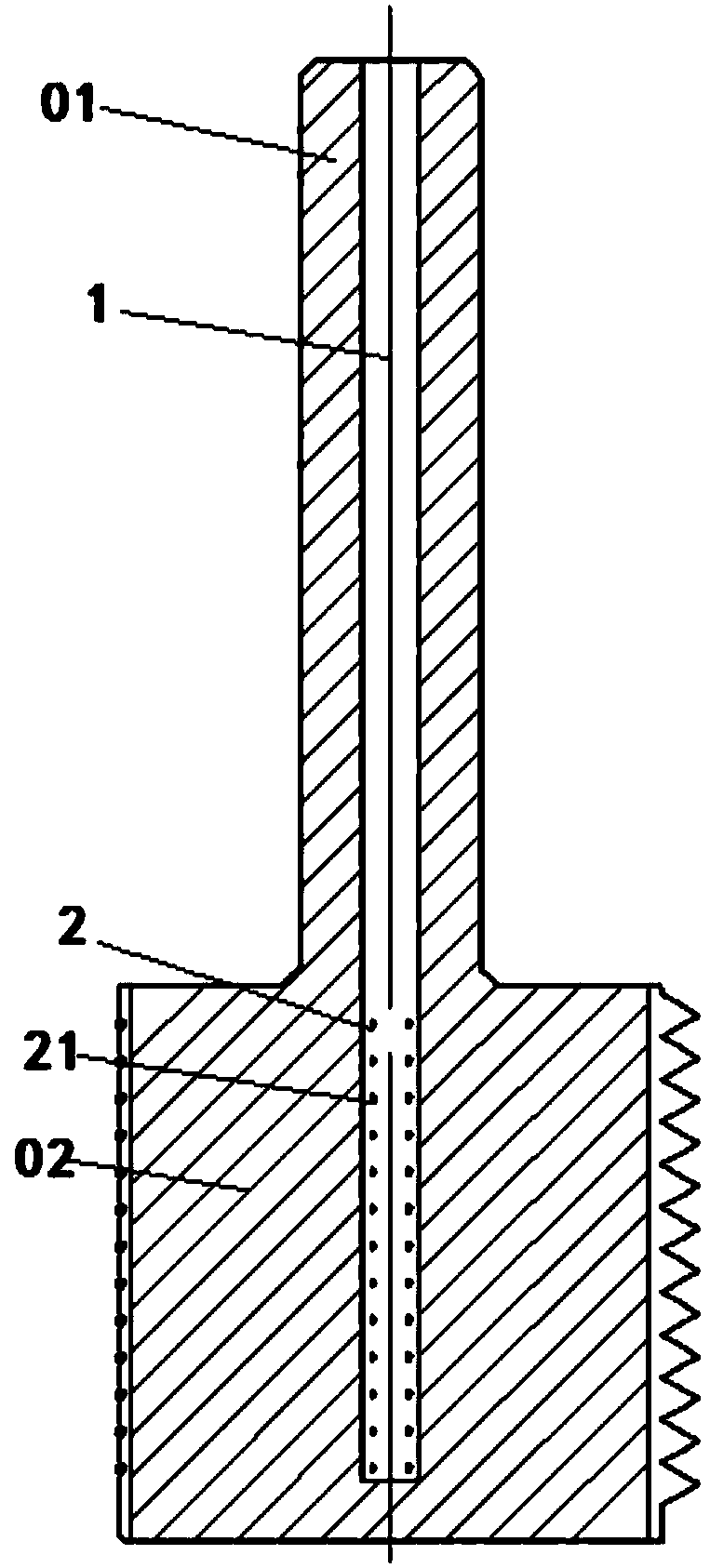
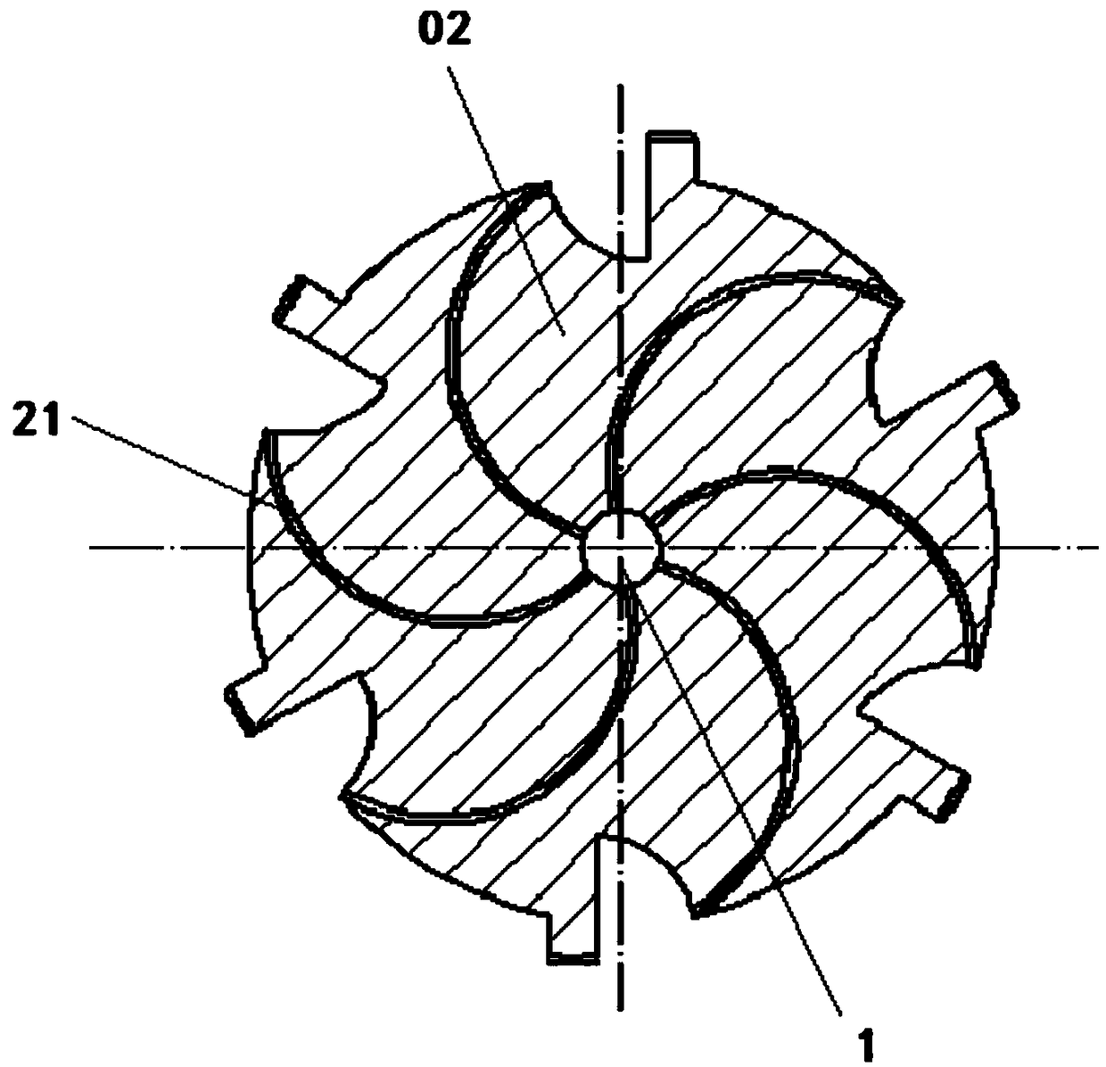
[0039] like figure 1 and figure 2 As shown, a tap with a self-cooling and lubricating structure includes a tap shank 01, a tap head 02, and a cooling lubricant main channel 1; the cooling lubricant main channel is arranged in the tap shank 01 and the tap head 02 along the axial direction 1. Cooling and lubricating liquid sub-flow channels 2 are set in the tap head 02, and multiple groups are arranged in sequence along the cooling and lubricating liquid flow direction in the cooling and lubricating liquid main channel 1; each group of cooling and lubricating liquid sub-flow channels 2 is evenly distributed in the circumferential direction Composed of a plurality of branched cooling and lubricating flow channels 21 (each branched cooling and lubricating flow channel 21 is opened radially), one end of each branched cooling and lubricating flow channel 21 communicates with the cooling and lubricating liquid main flow channel, and the other end faces the tapping area; The branche...

Embodiment 2

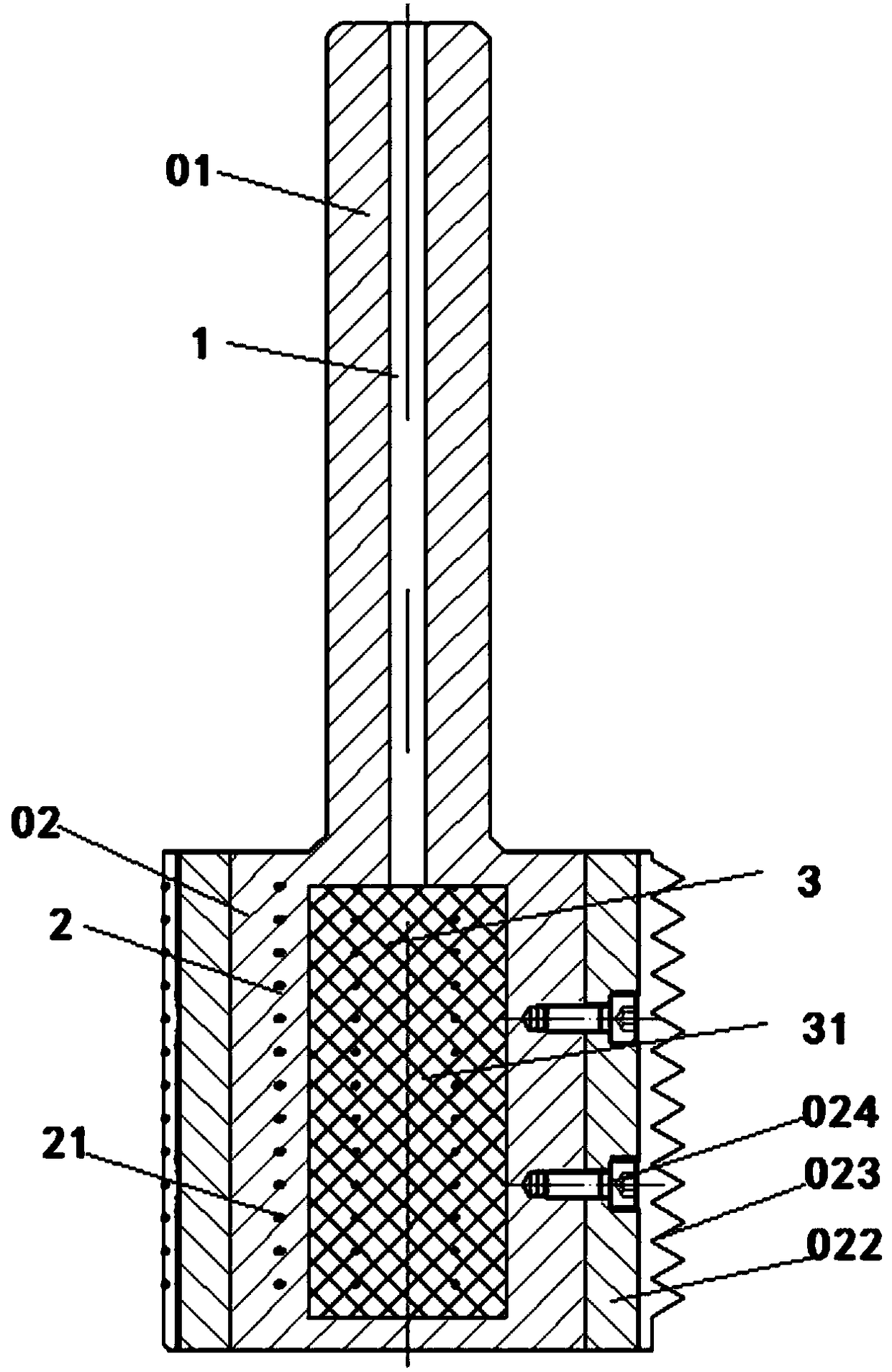
[0041] like image 3 and Figure 4 Shown, on the basis of embodiment 1, the present invention also has further optimized design:

[0042] 1. A temporary cooling and lubricating fluid storage area 3 is provided in the tap head 02. The cooling and lubricating fluid temporary storage area 3 includes a matrix 31 arranged between the cooling and lubricating fluid main flow channel 1 and multiple sets of cooling and lubricating fluid auxiliary flow channels 2. The base body 31 is provided with a plurality of pores connected from its center to the entire outer surface; the plurality of pores communicate the cooling lubricant main channel and the cooling lubricant secondary channel; the cooling lubricant flows through the cooling lubricant main channel 1 to the cooling lubricant temporary storage Zone 3, so that the cooling lubricant can be temporarily stored at this position before the tap is ready for tapping, and the cooling lubricant can pass through the branch cooling lubricant ...


PUM


Abstract

The invention particularly relates to a screw tap with a self-lubricating cooling structure. The screw tap comprises a screw tap handle, a screw tap head and a cooling lubricating fluid main runner, the cooling lubricating fluid main runner is axially arranged in the screw tap handle and the screw tap head, and further comprises a cooling lubricating liquid auxiliary flow channel, the cooling lubricating liquid auxiliary flow channel is arranged in the screw tap head, a plurality of groups of cooling lubricating liquid are sequentially arranged along the flow direction of the cooling lubricating liquid in the cooling lubricating fluid main flow channel, each group of cooling lubricating fluid sub-flow channels is composed of a plurality of branch cooling and lubricating flow channels whichare uniformly distributed in the circumferential direction, one end of each branch cooling lubricating flow channel is communicated with the cooling lubricating liquid main flow channel, the other end of each branch cooling lubricating flow channel faces the tapping area, the branch cooling and lubricating flow channel is arc-shaped, the screw tap handle, the screw tap head and the cooling lubricating fluid main flow channel, and the cooling and lubricating fluid sub-runners are processed and formed in a 3D printing mode. According to the screw tap, the tapping area can be directly and uniformly cooled, and the cooling cost is low.

Description

technical field [0001] The invention relates to a machining tool, in particular to a screw tap with a self-lubricating cooling structure. Background technique [0002] According to the processing type, the cutting process is mainly divided into: turning, drilling, milling, boring and grinding; [0003] Turning refers to the use of the rotary motion of the workpiece and the linear or curved motion of the tool to change the shape and size of the blank; drilling refers to the process of using the tool to process holes on the workpiece; The blade tool moves on the blank to cut the workpiece into the required shape and size; boring is a cutting process that uses a tool to enlarge a hole or other circular contours; grinding refers to the processing method of removing excess material on the workpiece with abrasives , which belongs to the finishing machining of mechanical processing; [0004] The tap is also a tool used for cutting, but its special type is relatively strong, and i...

Claims


Application Information

Patent Timeline
Patent Type & Authority Applications(China)
IPC IPC(8): B23G5/06
CPCB23G5/06B23G2200/06
Inventor 王磊张琼赵纪元卢秉恒
Owner XI AN JIAOTONG UNIV
Why Eureka
Try Eureka