Silk-screen printing equipment

A technology of screen printing and equipment, applied in screen printing, screen printing machines, printing, etc., can solve problems such as labor-intensive, difficult to control precision, irregular arrangement, etc., to achieve convenient absorption, reduce labor costs, and automation high effect

Pending Publication Date: 2019-02-19
JIANGSU GIS LASER TECH INC
View PDF0 Cites 5 Cited by
  • Summary
  • Abstract
  • Description
  • Claims
  • Application Information

AI Technical Summary

Problems solved by technology

However, this screen printing host mainly has the following disadvantages: the current screen printing host first takes out the bottom plate, then manually places the mobile phone case on the bottom plate, and then puts the bottom plate on the workbench for exposure, and then The arrangement of the mobile phone case is irregular. When the exposure head is exposed, a CCD camera is required to detect and align the edge of each case, and then uniformly expose to form the pattern on the mobile phone case. However, the arrangement is not correct due to manual placement. Regular, and the number of mobile phone cases is large, it is difficult to detect edge alignment, and the calculation is complicated. At the same time, the placement and loading of mobile phone cases on the bottom plate are manual, the operation is more complicated, and it takes a lot of labor. At the same time, the mobile phone case It is not well fixed on the bottom plate, but is positioned by an L-shaped positioning rod. Therefore, it is more likely to have a large deviation during the moving process, which will affect the accuracy of exposure and the effect of pattern generation.
The mobile phone case needs to be moved horizontally and vertically to expose when placed on the bottom plate, so the error of the moving parts will affect the exposure accuracy, especially when the mobile phone case is arranged irregularly, the accuracy is more difficult to control

Method used


Image

  • Silk-screen printing equipment
  • Silk-screen printing equipment
  • Silk-screen printing equipment

Examples


Embodiment Construction

[0035] The present invention will be described in further detail below through specific examples.

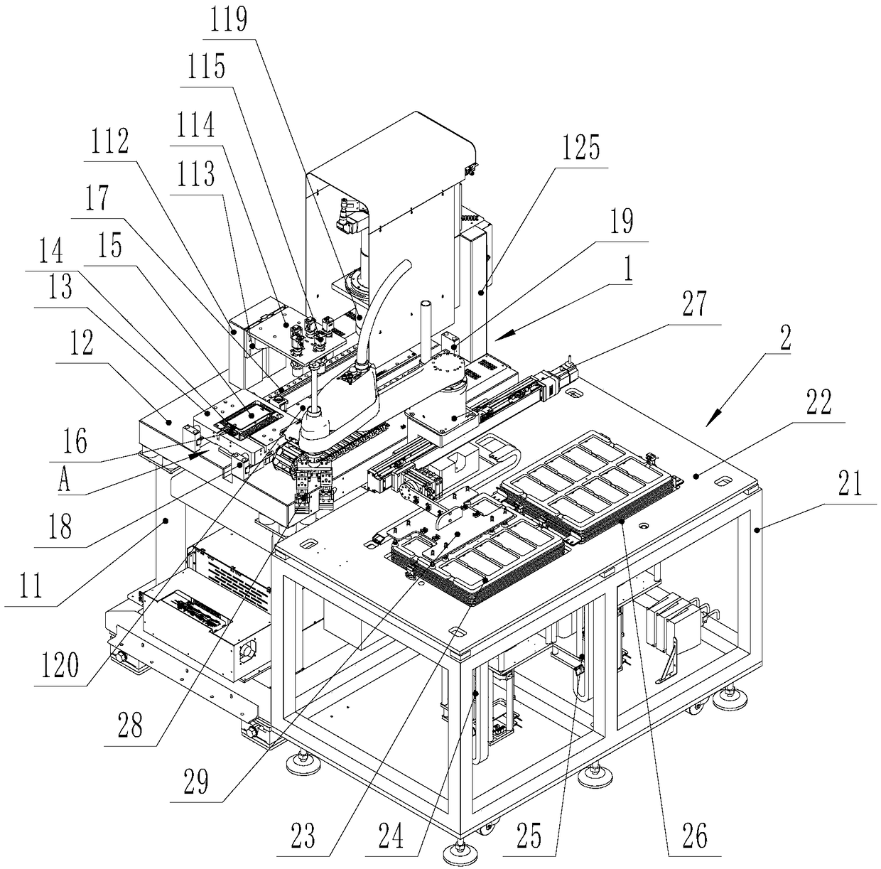
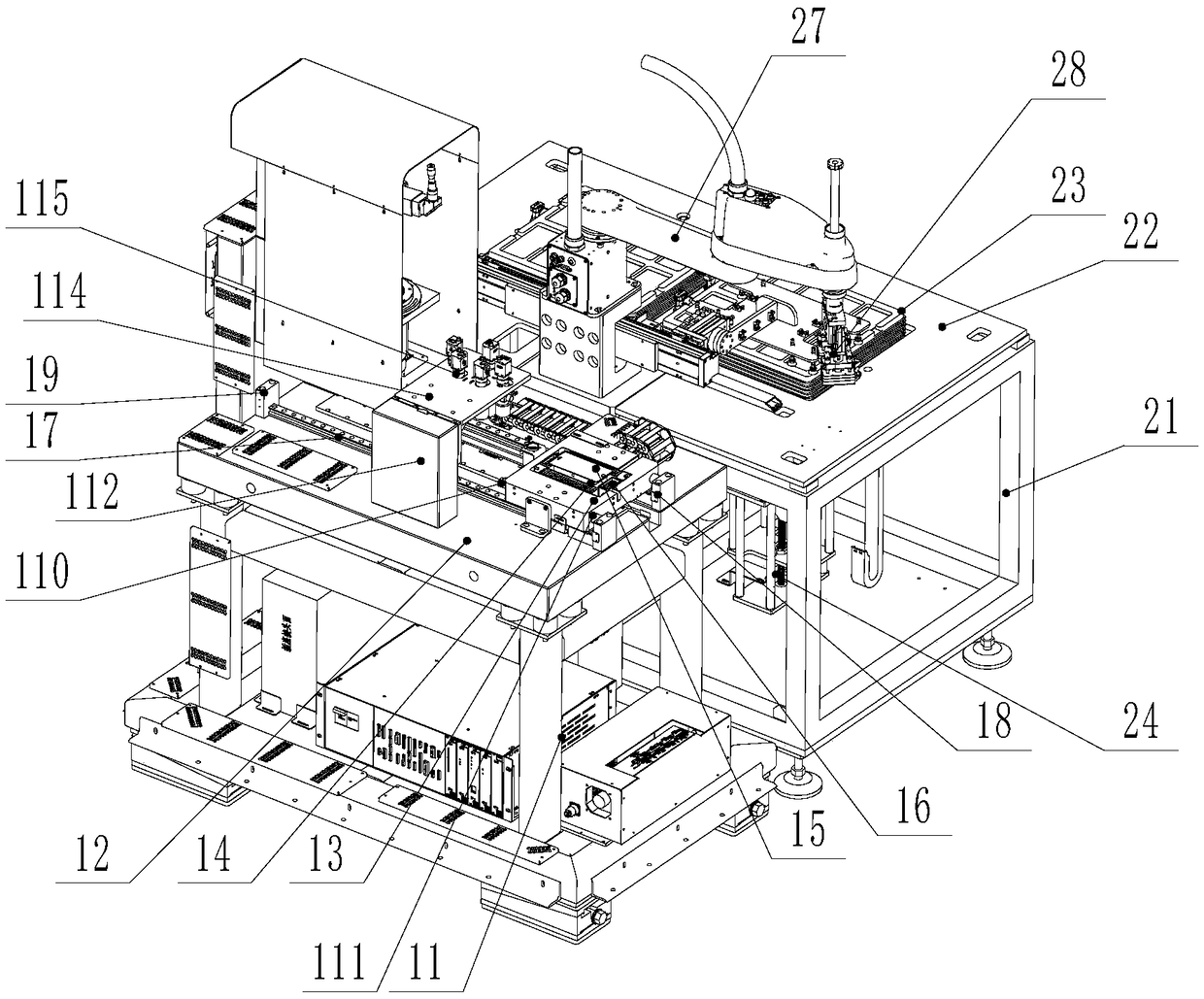
[0036] Such as figure 1 and figure 2 As shown, a screen printing equipment includes an exposure host 1 , and the screen printing equipment also includes an automatic feeding device 2 , which is arranged on one side of the exposure host 1 .

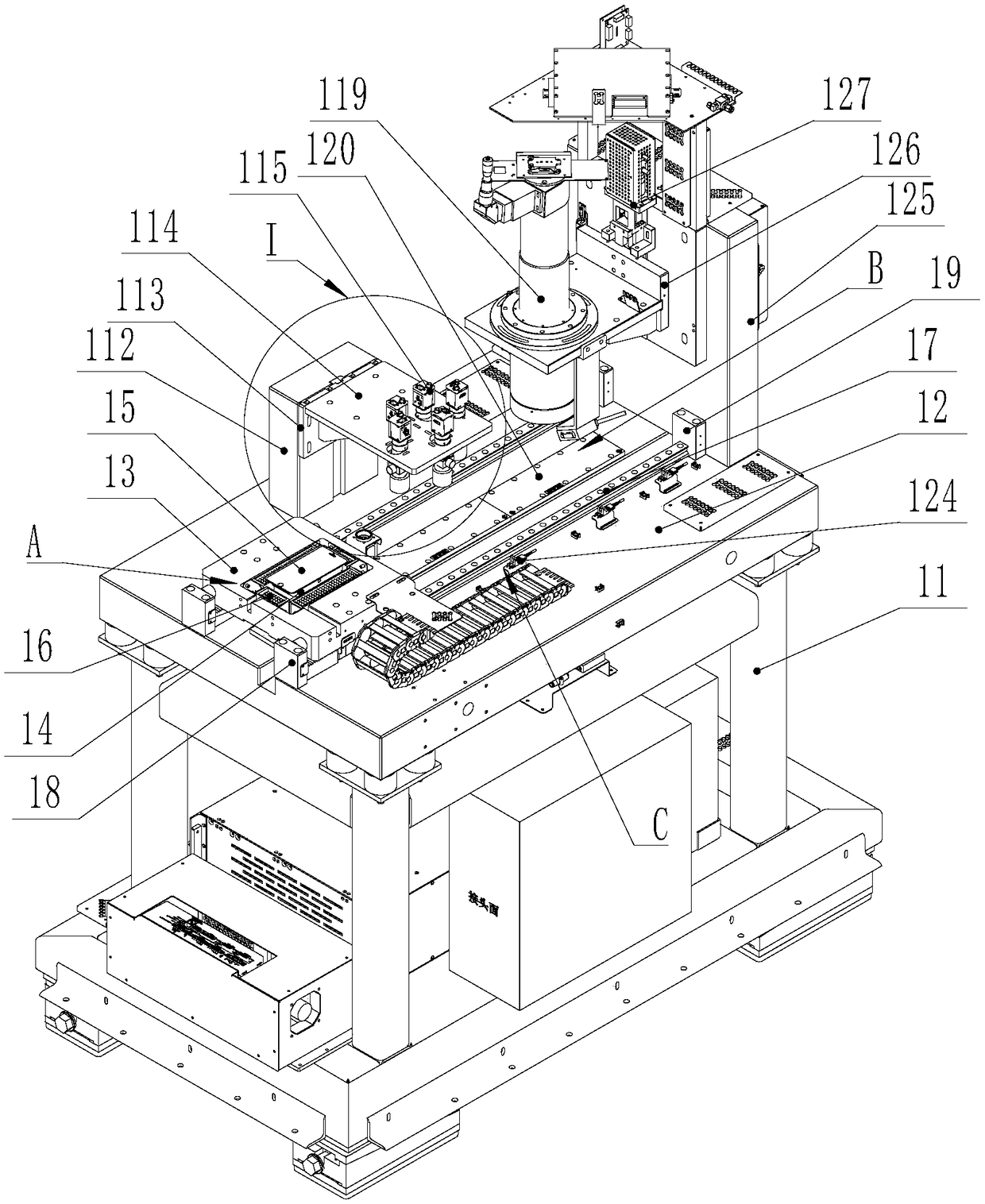
[0037] Such as Figure 3 to Figure 6 As shown, the exposure main frame 1 includes an exposure frame 11, and the exposure frame 11 is provided with a workbench 12, on which a horizontal sliding seat 13 is horizontally slidably installed, and the horizontal sliding seat 13 is driven by a horizontal power device. Drive to slide between the feeding station A and the exposure station B, the horizontal sliding seat 13 is equipped with a vacuum adsorption seat 14 for vacuum adsorption of the mobile phone case 15, the vacuum adsorption seat 14 communicates with the vacuum system, the A support seat 125 is installed on the workbench 12, and a ver...


PUM


Abstract

The invention discloses silk-screen printing equipment. The silk-screen printing equipment comprises an exposure main engine, and further comprises an automatic feeding device; the automatic feeding device is arranged at one side of the exposure main engine; the exposure main engine comprises a worktable; the worktable is provided with a feeding station and an exposure station; the exposure station is provided with an exposure head; the automatic feeding device comprises a feeding platform; the feeding platform is provided with a manipulator; the end of the manipulator is provided with first suction cup components; the manipulator can be switched between a supplement station and the feeding station to deliver trays to the feeding station; and the feeding platform is provided with a transfer device used for transferring the trays to a finished product storage station. The printing equipment is capable of realizing automatic feeding, exposure and discharging of mobile phones, and is higher in automation degree, and reduces labor cost.

Description

technical field [0001] The invention relates to a screen printing device, which is used for exposing the surface of a mobile phone case to form a pattern. Background technique [0002] The original screen printing equipment includes an exposure host, and the exposure host includes a frame. A crossbeam is slidably installed, a transverse sliding seat is slidably installed on the crossbeam along the transverse direction, and an exposure head is installed on the transverse sliding seat. However, this screen printing host mainly has the following disadvantages: the current screen printing host first takes out the bottom plate, then manually places the mobile phone case on the bottom plate, and then puts the bottom plate on the workbench for exposure, and then The arrangement of the mobile phone case is irregular. When the exposure head is exposed, a CCD camera is required to detect and align the edge of each case, and then uniformly expose to form the pattern on the mobile phon...

Claims


Application Information

Patent Timeline
IPC IPC(8): B41F15/12B41F15/14B41F15/20B41F33/00B41F33/16
CPCB41F15/12B41F15/14B41F15/20B41F33/0036B41F33/16B41P2200/40B41P2215/50B41P2215/114Y02P70/50
Inventor 潘钰朱鹏飞吴景舟马迪
Owner JIANGSU GIS LASER TECH INC
Why Eureka
Try Eureka