Method of secondary sedimentation tank in sewage treatment by replacing biochemical method and structure of method

A technology of sewage treatment and secondary sedimentation tank, which is applied in the fields of flotation water/sewage treatment, water/sewage multi-stage treatment, water/sludge/sewage treatment, etc. The hydraulic retention time of the pool is caused by the floating of sludge and the difficulty of ensuring the stability of the effluent to meet the standard, so as to achieve the effect of improving the water treatment capacity per unit area, reducing the solid load and improving the effluent effect.

Inactive Publication Date: 2019-02-19
SHENZHEN QINGQUAN WATER IND CO LTD
View PDF3 Cites 2 Cited by
  • Summary
  • Abstract
  • Description
  • Claims
  • Application Information

AI Technical Summary

Problems solved by technology

[0003] At present, the commonly used pool structures of secondary sedimentation tanks are divided into advection type, radial flow type, and vertical flow type, all of which generally have a long hydraulic retention time (4-6hr), which is likely to cause sludge denitrification to generate nitrogen, or anaerobic metabolism. produce a lot of H 2 S, CH 4 and other gases, making the air bubbles attach to the sludge flocs, causing the sludge to float
On the one hand, the current urbanization process in the country is fast, and it is difficult for most sewage treatment plants to acquire land for expansion, which makes the problem of limited land occupation for standard upgrading and capacity expansion; on the other hand, excessive hydraulic retention time in sedimentation tanks can easily cause sludge to float , causing the effluent SS to exceed the standard
These factors have seriously restricted the process of standard upgrading and transformation of sewage treatment plants, and it is difficult to ensure that the effluent can meet the standard stably

Method used


Image

  • Method of secondary sedimentation tank in sewage treatment by replacing biochemical method and structure of method
  • Method of secondary sedimentation tank in sewage treatment by replacing biochemical method and structure of method
  • Method of secondary sedimentation tank in sewage treatment by replacing biochemical method and structure of method

Examples


Embodiment Construction

[0020] The present invention will be described in further detail below in conjunction with the accompanying drawings.

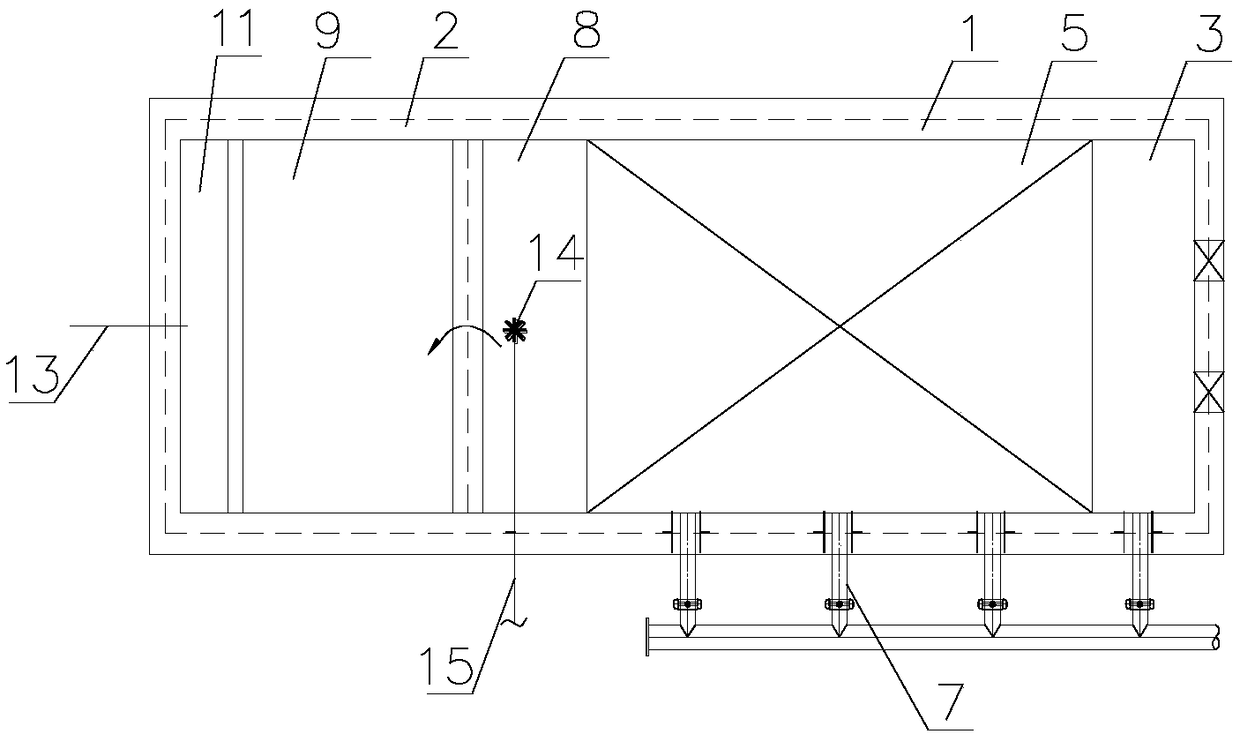
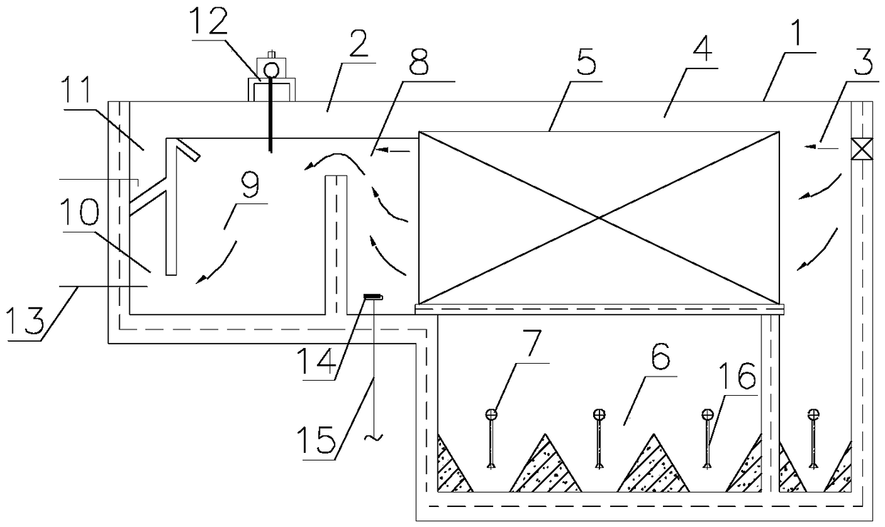
[0021] Such as Figure 1 to Figure 2 As shown, a method and structure for replacing the secondary sedimentation tank of biochemical sewage treatment, including a lateral flow sedimentation tank 1 and an air flotation tank 2, and the lateral flow sedimentation tank 1 is provided with an inflow buffer zone 3 and a sedimentation zone 4 , sludge area 6, sludge discharge pipe 7; the air flotation tank 2 is provided with a contact area 8, a separation area 9, a water collection area 10, a slag discharge area 11, a slag scraper 12, and a releaser 14;

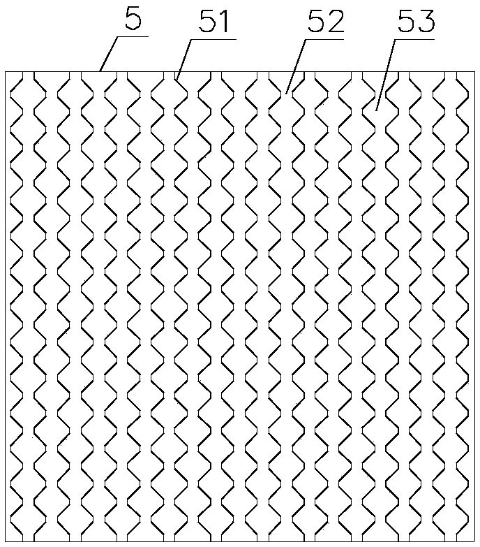
[0022] A solid-liquid separation assembly 5 is installed in the settling area 4, a sludge area 6 is provided directly below the solid-liquid separation assembly 5, a sludge discharge pipe 7 is arranged in the sludge area, and the releaser 14 is located at At the bottom of the water inlet end of the contact area 8 , t...


PUM


Abstract

The invention relates to a method of a secondary sedimentation tank in sewage treatment by replacing a biochemical method and a structure of the method. The structure comprises a lateral flow sedimentation tank and an air flotation tank, and is characterized in that the method specifically includes the following steps that: (1) effluent water from a biochemical tank enters into the lateral flow sedimentation tank, large-particle sludge particles are rapidly separated in a solid-liquid separation component, and precipitated sludge flows back to a front end biochemical tank; (2) the effluent water from the lateral flow sedimentation tank is quickly separated from small-particle sludge and scum on the water surface through the air flotation tank, and the sludge and the scum are removed. The hydraulic retention time of the secondary sedimentation tank water is greatly shortened, the occupied area is saved, the problem of floating sludge commonly existing in the secondary sedimentation tankis solved, and the effluent water quality is guaranteed. The method can be used for upgrading the standard of sewage treatment plants and for building new sewage treatment plants.

Description

technical field [0001] The invention relates to the field of water treatment, in particular to a method and structure for substituting a biochemical sewage treatment secondary sedimentation tank. Background technique [0002] As an important part of the biochemical activated sludge sewage treatment process, the secondary settling tank is mainly used to realize the separation of mud and water, to clarify and concentrate the mixed solution, and then to return the sludge to ensure the concentration of activated sludge in the whole system, and its working effect It will directly affect the effluent water quality and return sludge concentration of the activated sludge system. [0003] At present, the commonly used pool structures of secondary sedimentation tanks are divided into advection type, radial flow type, and vertical flow type, all of which generally have a long hydraulic retention time (4-6hr), which is likely to cause sludge denitrification to generate nitrogen, or anae...

Claims


Application Information

Patent Timeline
Patent Type & Authority Applications(China)
IPC IPC(8): C02F9/02B01D21/02
CPCB01D21/0075B01D21/02C02F1/24C02F2001/007
Inventor 叶昌明伍波
Owner SHENZHEN QINGQUAN WATER IND CO LTD
Why Eureka
Try Eureka