
Exhaust gas recirculation system and engine

A recirculation system and engine technology, applied in the direction of exhaust gas recirculation, engine components, combustion engines, etc., can solve the problems of increased pumping loss, economic deterioration, and difficulty in obtaining sufficient EGR rate, etc.

Inactive Publication Date: 2019-02-19
WEICHAI POWER CO LTD
View PDF8 Cites 2 Cited by
  • Summary
  • Abstract
  • Description
  • Claims
  • Application Information

AI Technical Summary

Problems solved by technology

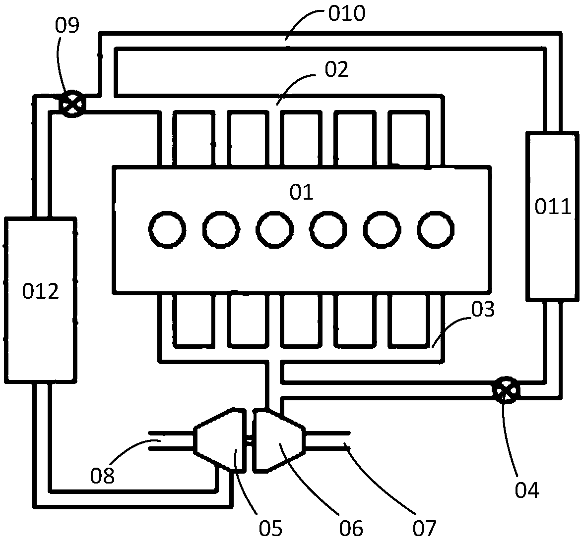
[0003] Existing EGR systems such as figure 1 As shown, the exhaust manifold 03 of the engine 01 is connected to the turbine 06 of the turbocharger, the exhaust pipe 07 is connected behind the turbine 06, one end of the EGR pipeline 010 takes air from the front of the turbine 06, and the other end is connected to the engine 01 The intake manifold 02 is provided with an EGR valve 04 on the EGR pipeline, the inlet of the compressor 05 of the turbocharger is connected to the intake pipe 08, and the outlet of the compressor 05 communicates with the intake manifold 02. When the EGR valve is opened, part of The exhaust gas enters the turbine 05 to pressurize the intake air, and the remaining exhaust gas passes through the EGR valve 04 and the EGR cooler 011, mixes with the pressurized air, and then enters the intake manifold 02 of the engine 01. Due to the improvement of the efficiency of the turbocharger, the increase The intake pressure after compression will be higher than the exhaust pressure in front of the vortex in a relatively large speed range, and it is difficult to obtain a sufficient EGR rate simply by opening the EGR valve
In order to obtain a sufficiently large and adjustable EGR rate, reduce NO x , the commonly used method is the intake throttle valve 09 on the intake line, the EGR exhaust gas is mixed with the charge air downstream of the intake throttle valve 09, but the intake throttle valve 09 will significantly increase the pump while increasing the EGR rate Gas loss, resulting in increased engine fuel consumption, increased particulate matter emissions, resulting in economical deterioration

Method used


Image

  • Exhaust gas recirculation system and engine
  • Exhaust gas recirculation system and engine
  • Exhaust gas recirculation system and engine

Examples


Embodiment 1

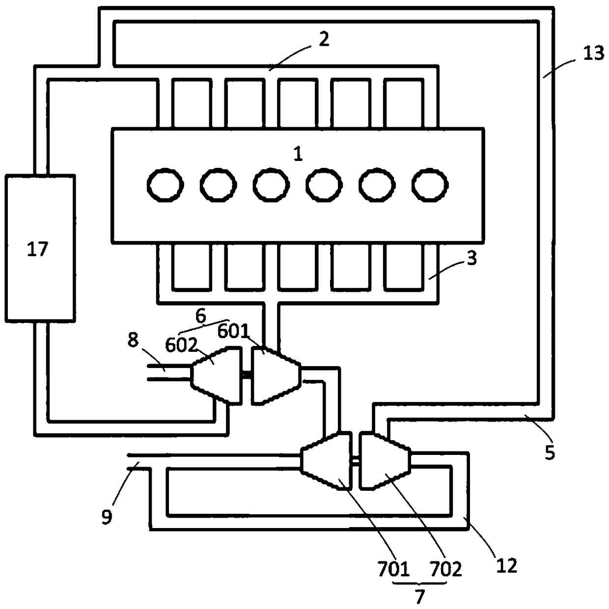
[0044] see figure 2 , the inlet of the turbine 601 of the first turbocharger 6 communicates with the exhaust manifold 3 of the engine 1, the outlet of the turbine 601 of the first turbocharger 6 communicates with the inlet of the turbine 701 of the second turbocharger 7, and the second turbine The outlet of the turbine 701 of the supercharger 7 is connected to the exhaust pipe 9, the inlet of the compressor 602 of the first turbocharger 6 is connected to the intake pipe 8, and the outlet of the compressor 602 of the first turbocharger 6 is connected to the engine through the intercooler 17. 1 The intake manifold 2 communicates, the inlet of the compressor 702 of the second turbocharger 7 communicates with the exhaust pipe 9, and the outlet of the compressor 702 of the second turbocharger 7 communicates with the intake manifold 2.

[0045] In the above-mentioned structure, the exhaust gas discharged from the engine 1 first enters the turbine 601 of the first turbocharger 6 to ...

Embodiment 2

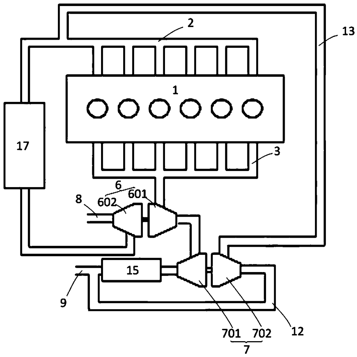
[0047] see image 3 ,and figure 2 The difference of the illustrated embodiment is that the EGR air intake pipe 12 takes air from the post-processing system 15 , and the exhaust gas is relatively clean after being processed by the post-processing system 15 , which can reduce pollution to the engine 1 .

Embodiment 3

[0049] see Figure 4 , Figure 4 The example shown is in image 3 On the basis of the embodiment, a high-pressure EGR exhaust gas pipe 4 is added, and the high-pressure EGR exhaust gas pipe 4 will directly take exhaust gas from the front of the turbine 601 of the first turbocharger 6, and pass the exhaust gas into the intake manifold of the engine 1 2, in this way, a dual-channel EGR system is formed, and the high-pressure EGR exhaust gas pipe 4 or the low-pressure EGR exhaust gas pipe 5 can be opened as required.


PUM


Abstract

The invention discloses an exhaust gas recirculation system and an engine. The exhaust gas recirculation system comprises a first turbosuperchager and a second turbosuperchager which are in series connection. An outlet of a power turbine of the second turbosuperchager is connected with an exhaust pipe, an inlet of a gas compressor of the second turbosuperchager communicates with the exhaust pipe through an EGR gas getting pipe, an outlet of the gas compressor of the second turbosuperchager communicates with a gas inlet manifold through a low-pressure EGR waste gas pipe, the system repeatedly uses waste gas energy to push power turbines of the two stages of turbosuperchagers, the waste gas use rate is improved, energy losses brought by front getting of waste gas of the turbosuperchagers canbe reduced, the first turbosuperchager can be matched with the efficient gas compressor, the oil losses are reduced, the exhaust temperature is improved, the conversion efficiency of a post-treatmentsystem is improved, meanwhile, the EGR gas pressure and waste gas amount can be improved, a gas inlet throttling valve is not needed, the conditions of pump gas losses, engine oil consumption increasing, particle discharge increasing and the like are avoided, and engine economy is improved.

Description

technical field [0001] The invention relates to the technical field of engine EGR, in particular to an exhaust gas recirculation system and an engine. Background technique [0002] Exhaust gas recirculation (EGR) is a modern diesel engine to reduce NO x One of the most effective means of emission. EGR can reduce the oxygen concentration and maximum combustion temperature in the cylinder to reduce NO x Effect. EGR is considered to be one of the important technical means for diesel engines to meet China IV and later emission regulations. [0003] Existing EGR systems such as figure 1 As shown, the exhaust manifold 03 of the engine 01 is connected to the turbine 06 of the turbocharger, the exhaust pipe 07 is connected behind the turbine 06, one end of the EGR pipeline 010 takes air from the front of the turbine 06, and the other end is connected to the engine 01 The intake manifold 02 is provided with an EGR valve 04 on the EGR pipeline, the inlet of the compressor 05 of t...

Claims


Application Information

Patent Timeline
IPC IPC(8): F02M26/08F02M26/14F02M26/34F02B37/013
CPCF02B37/004F02B37/013F02M26/08F02M26/14F02M26/34Y02T10/12
Inventor 战强褚国良
Owner WEICHAI POWER CO LTD
Learn More