A pressure testing system and method in concrete target under ultra-high-speed penetration conditions

A technology for pressure testing and concrete, applied in force/torque/work measuring instruments, measuring devices, measuring blasting force, etc. It can solve the problem of affecting the test accuracy, the inability to accurately measure the pressure distribution of the shock wave propagation law of the kinetic energy rod, and the sensor displacement, etc. question

Active Publication Date: 2020-11-13
BEIJING INSTITUTE OF TECHNOLOGYGY
View PDF7 Cites 0 Cited by
  • Summary
  • Abstract
  • Description
  • Claims
  • Application Information

AI Technical Summary

Problems solved by technology

The test of the ultra-high-speed penetration of the kinetic energy rod into the concrete target studies the damage to the overall concrete target caused by the penetration of the projectile. However, the existing test method fixes multiple sensors on different concrete blocks, and then fixes them in the target hoop. The target is a split structure as a whole, and the split concrete target affects the accuracy of the test
There are also some pouring concrete targets. Although the concrete target has an integrated structure, it does not solve the problem of sensor displacement during the pouring process, which affects the test accuracy.
[0005] In summary, the existing test methods and methods cannot accurately measure the shock wave propagation law and the pressure distribution in the target during the ultra-high-speed penetration of the kinetic energy rod into the concrete target.

Method used


Image

  • A pressure testing system and method in concrete target under ultra-high-speed penetration conditions
  • A pressure testing system and method in concrete target under ultra-high-speed penetration conditions
  • A pressure testing system and method in concrete target under ultra-high-speed penetration conditions

Examples


Embodiment Construction

[0039] The present invention will be described in detail below with reference to the accompanying drawings and examples.

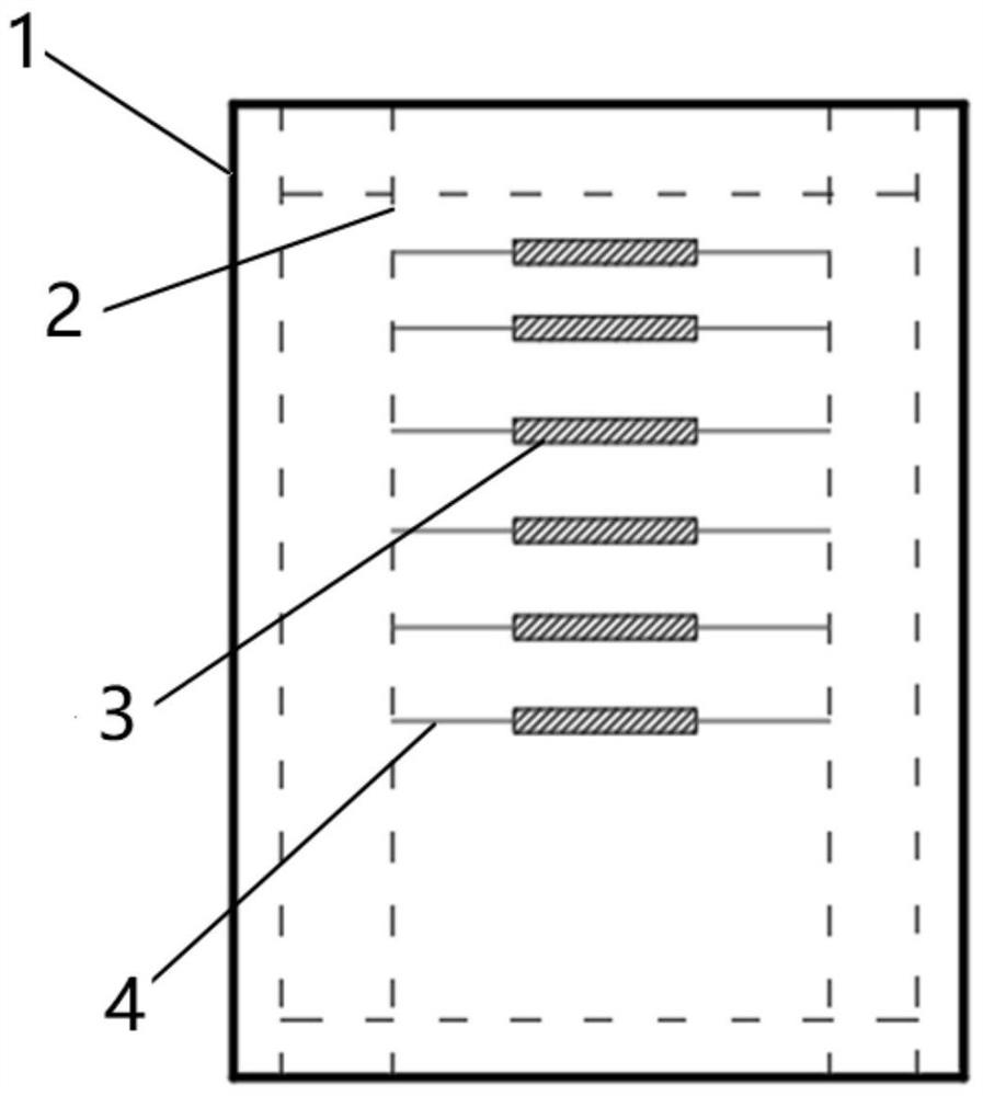
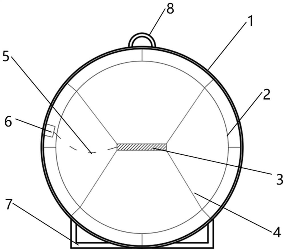
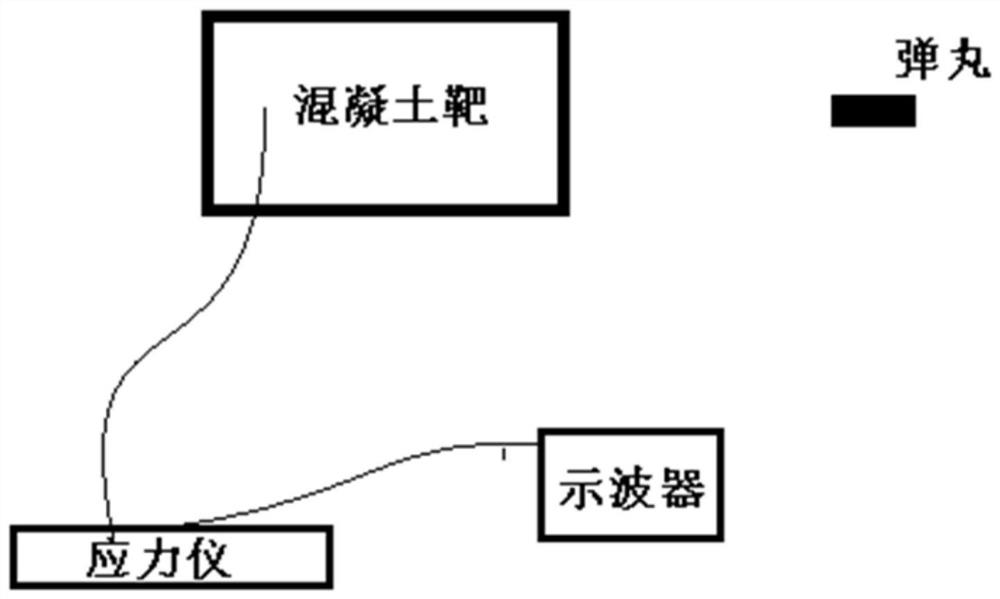
[0040] The present invention provides a concrete target pressure test system under ultra-high-speed penetration conditions, including a target hoop 1, a steel frame 2, a packaged sensor assembly 3, a rubber rope 4, concrete, a stress meter and an oscilloscope, such as figure 1 shown.

[0041] Encapsulation sensor assembly 3 comprises manganin piezoresistive sensor 11, encapsulation bottom plate 9, encapsulation cover plate 10 and coaxial cable 13, as Figure 4 , Figure 5 As shown, the sensitive element 12 of the manganin piezoresistive sensor 11 is located at the center of the package base plate 9, and the package cover plate 10 seals other parts of the manganin piezoresistive sensor 11 except the solder joint 14; the solder joint 14 of the manganese copper piezoresistive sensor 11 The coaxial cable 13 is welded, and the welding spot 14 is potted with h...


PUM

PropertyMeasurementUnit
thicknessaaaaaaaaaa

Abstract

The invention provides a system and a method for testing a pressure in a concrete target under a super speed penetration condition. The system for testing the pressure comprises a target hoop, a rebarframe, packaging sensor assemblies, rubber ropes, concrete, a stress instrument, and an oscilloscope. One or more packaging sensor assemblies are arranged on the rebar frame through the rubber ropes,and the rubber ropes have a certain pre-tightening force, so that the positions of the packaging sensor assemblies can be recovered to original positions after the positions of the packaged sensor assemblies changes in the concrete pouring process. The rebar frame is fixed on the target hoop, and concrete is poured into the target hoop to form the concrete target. The packaging sensor assembliesare connected with the stress instrument. A pressure signal representative of a shock wave propagation rule in the target and the pressure distribution in the target is displayed by the oscilloscope to obtain a pressure curve after processing. According to the system and the method for testing the pressure in the concrete target under the super speed penetration condition, the pressure testing precision is improved, the reliability of the testing data is guaranteed, and the accurate shock wave propagation rule in the target and the pressure distribution in the target are provided.

Description

technical field [0001] The invention relates to the technical field of ultra-high-speed penetration damage effect evaluation, in particular to a pressure test system and method for concrete targets under ultra-high-speed penetration conditions. Background technique [0002] The research on the penetration damage of the kinetic energy penetrating warhead to concrete has always been a hot issue in the weapon development department. Under the conditions of air strikes in modern warfare, it is difficult for ground military targets to survive, and the defense structures of targets with important strategic value (such as underground fortifications, hangars, command and communication facilities, etc.) are becoming stronger and stronger. In order to strike such high-value targets more effectively, the research of ground-penetrating bombs has attracted more and more attention from all over the world. The ground-penetrating projectile is a precision-guided attack projectile that carr...

Claims


Application Information

Patent Timeline
Patent Type & Authority Patents(China)
IPC IPC(8): G01L5/14G01L5/162
CPCG01L5/14G01L5/162
Inventor 陆阳予张庆明龙仁荣薛一江商成刘岩
Owner BEIJING INSTITUTE OF TECHNOLOGYGY
Why Eureka
Try Eureka