
Pseudolite system and method based on GNSS precision time service

A pseudolite, sophisticated technology, applied in the field of surveying, mapping and navigation, which can solve the problems of inability to meet precise positioning, vulnerable channels to interference, and expensive equipment.

Active Publication Date: 2019-02-19
WUHAN UNIV
View PDF5 Cites 26 Cited by
  • Summary
  • Abstract
  • Description
  • Claims
  • Application Information

AI Technical Summary

Problems solved by technology

The use of wired channels has strong anti-interference ability, but the laying period is long, the equipment cost is expensive, and the distance between stations is also limited.
Wireless channels are susceptible to interference, and stability is difficult to guarantee
In addition, the transmitter requires additional circuits for data reception and decoding, which increases the complexity and cost of system design
[0007] (2) Using the standard pseudo-range GNSS single-point positioning technology can realize the time synchronization between the ground pseudolite and the GNSS system. This method is relatively simple to implement, but the time synchronization accuracy is on the order of tens of nanoseconds
Deploying pseudo-satellite base stations with a time synchronization better than 0.3 nanoseconds within a certain range can combine with GNSS to obtain real-time positioning accuracy better than 10 centimeters, which can meet the needs of UAV formation flight, lane-level automatic driving, automatic parking, robot navigation, etc. The demand for high-precision positioning, and the method of time synchronization by pseudo-range single-point positioning can only obtain a positioning accuracy of a few meters, which cannot meet the needs of precise positioning

Method used


Image

  • Pseudolite system and method based on GNSS precision time service
  • Pseudolite system and method based on GNSS precision time service
  • Pseudolite system and method based on GNSS precision time service

Examples


Embodiment Construction

[0090] In order to make the object, technical solution and advantages of the present invention more clear, the present invention will be further described in detail below in conjunction with the examples. It should be understood that the specific embodiments described here are only used to explain the present invention, not to limit the present invention.

[0091] At present, more accurate time synchronization methods all use differential timing methods, which rely on wired or wireless channels between transmitters for signal or information transmission. The use of wired channels has strong anti-interference ability, but the cost is expensive, and the distance between stations is also limited. Wireless channels are susceptible to interference, and stability is difficult to guarantee. In addition, the transmitter requires additional circuits for data reception and decoding, which increases the complexity and cost of the system.

[0092] The pseudolite synchronization method b...


PUM


Abstract

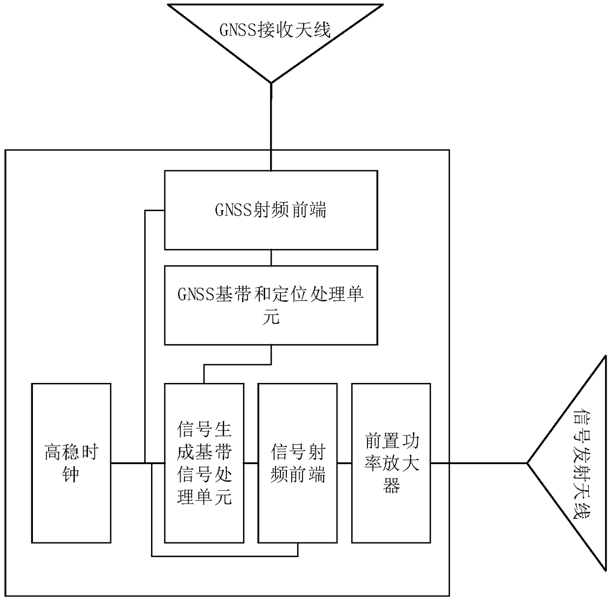
The invention belongs to the field of mapping and navigation, and discloses a pseudolite system and a method based on GNSS(Global Navigation Satellite System) precision time service. The method comprises the following steps: driving a GNSS receiver and a pseudolite signal transmitter by utilizing a homologous crystal oscillator, and solving a clock difference of a local clock of a receiver in realtime by utilizing a precision single point positioning model with coordinate constraint; eliminating a hardware delay between the signal transmitter and the GNSS receiver through a method of calibrating the hardware delay; and broadcasting an obtained clock difference of the local clock to a user in a form of electric files to realize a mathematical synchronization of the local clock and the GNSSsystem time. According to the pseudolite system and the method based on GNSS precision time service, the precision time synchronization of a single pseudolite system and a GNSS system can be realized, and a wired or wireless time synchronization link does not need to be constructed, so that the laying cost and hardware complexity are reduced; and the pseudolite system facilitates the joint positioning calculation with GNSS signals, so that the usability and the reliability of navigation positioning are improved.

Description

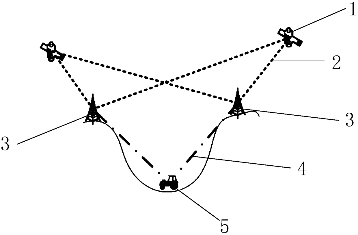
technical field [0001] The invention belongs to the field of surveying, mapping and navigation, and in particular relates to a pseudolite system and method based on GNSS precise time service. Background technique [0002] At present, the existing technologies commonly used in the industry are as follows: [0003] Pseudo-satellite technology achieves positioning by transmitting ranging signals from pseudo-satellite signal transmitters on the ground, which can effectively solve the positioning problem in scenarios where the global satellite navigation system (GNSS) cannot work, typical scenarios such as indoors, open-pit mines, and underground operations and tunnels etc. Similar to the principle of GNSS positioning, a pseudolite receiver needs to receive ranging signals from multiple transmitters to determine its own position. However, it is difficult to measure the geometric distance directly because the transmitter and receiver are not synchronized in time. Drawing on the...

Claims


Application Information

Patent Timeline
Patent Type & Authority Applications(China)
IPC IPC(8): G04R20/02G01S19/11
CPCG01S19/11G04R20/02
Inventor 王磊许钡榛张欣欣李涛陈锐志申丽丽
Owner WUHAN UNIV
Learn More