Bus-based servo motor synchronous control method
A servo motor, synchronous control technology, applied in the direction of a single motor speed/torque control, can solve the problem of complex control procedures, achieve the effects of high control accuracy, simple and efficient control procedures, and improve synchronous control accuracy
- Summary
- Abstract
- Description
- Claims
- Application Information
AI Technical Summary
Problems solved by technology
Method used
Image

Examples
specific Embodiment approach 1
[0021] Specific implementation mode one: combine figure 1 This embodiment is described, a bus-based servo motor synchronous control method provided in this embodiment specifically includes the following steps:
[0022] Step 1. The control system sends a dry run command to each servo driver, and obtains the response delay time of each servo motor corresponding to each servo driver by bus measurement; the bus control itself can detect the response delay time.
[0023] With the development of digital communication technology, field bus technology has been successfully introduced into the field of control, and has become a means of data exchange between functional modules such as computer numerical controllers (Computer Numerical Controller, CNC) and servo drives. Fieldbus has many advantages such as anti-interference, flexible communication, easy connection, and low cost, and it is the future development trend. At present, a situation in which multiple buses compete with each ot...
specific Embodiment approach 2
[0030] Specific embodiment 2: The difference between this embodiment and specific embodiment 1 is that the specific steps of using the bus measurement to obtain the response delay time of each servo motor corresponding to each servo driver in step 1 include:
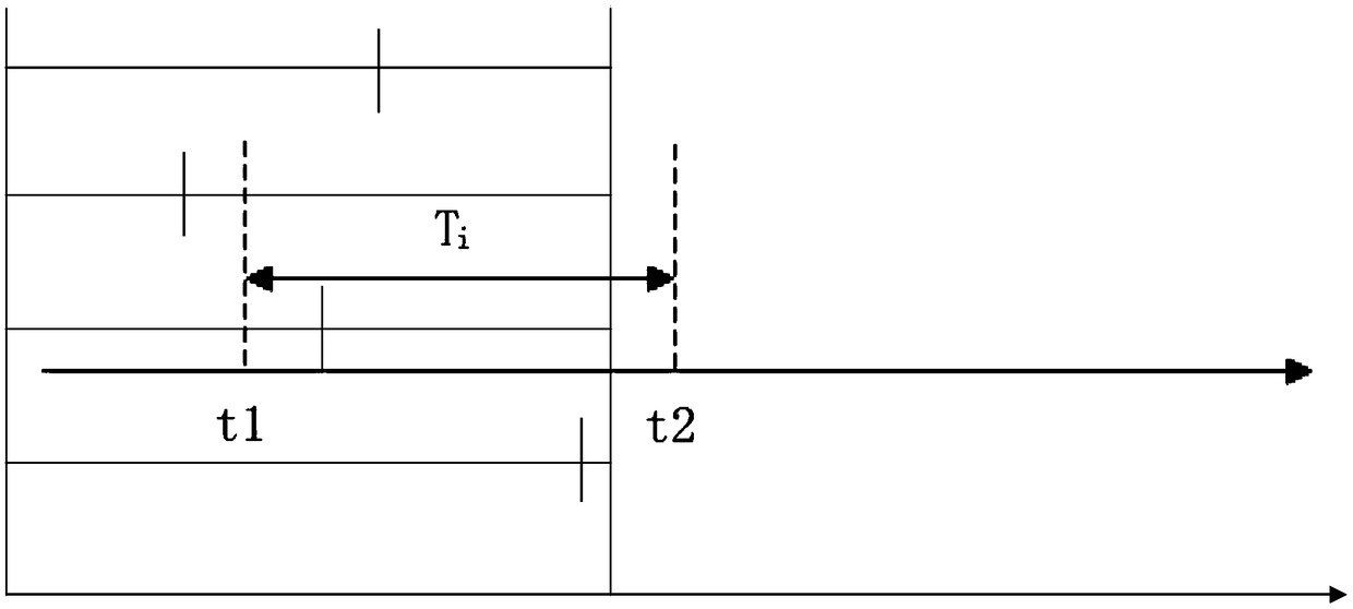
[0031] Step 11. The dry run command sent by the control system to each servo driver is sent in the form of a CAN message through the bus, and the servo drive returns a response after receiving the message, and the response field in the returned response determines that the servo drive has received the dry run The moment t1 of the instruction, and the moment t2 when the servo motor generates a response signal at the same time;
[0032] Step 1 and 2, the difference between t2 and t1 is the response delay time of the servo motor. like figure 2 As shown, the time between the two dotted lines is the response delay time Ti of the servo motor.
[0033] CAN is the abbreviation of Controller Area Network (CAN). It is an ISO in...
specific Embodiment approach 3
[0035] Embodiment 3: This embodiment is different from Embodiment 1 or Embodiment 2 in that in this embodiment, Y=X is selected.
[0036] The overall delay time of the control system is Y, and Y must be greater than or equal to X. Therefore, when Y=X is selected, the overall delay of the system is the smallest and the response effect is the best.
[0037] Other steps and parameters are the same as those in Embodiment 1 or 2.
PUM
 Abstract
Description
Claims
Application Information
 - R&D
- Intellectual Property
- Life Sciences
- Materials
- Tech Scout
- Unparalleled Data Quality
- Higher Quality Content
- 60% Fewer Hallucinations
Browse by: Latest US Patents, China's latest patents, Technical Efficacy Thesaurus, Application Domain, Technology Topic, Popular Technical Reports.
© 2025 PatSnap. All rights reserved.Legal|Privacy policy|Modern Slavery Act Transparency Statement|Sitemap|About US| Contact US: help@patsnap.com