Injector

A technology for syringes and syringes, applied in the field of syringes, which can solve the problems of cumbersome use of syringes and easy contamination of needles, and achieve the effects of rapid loading of liquid medicine, prevention of leakage and pollution, and easy operation

Inactive Publication Date: 2019-02-22
黄桂庭
View PDF6 Cites 12 Cited by
  • Summary
  • Abstract
  • Description
  • Claims
  • Application Information

AI Technical Summary

Problems solved by technology

[0005] The object of the present invention is: in order to solve the problems of cumbersome use of existing syringes and easy pollution of needles, the present invention provides a syringe

Method used


Image

  • Injector
  • Injector

Examples


Embodiment 1

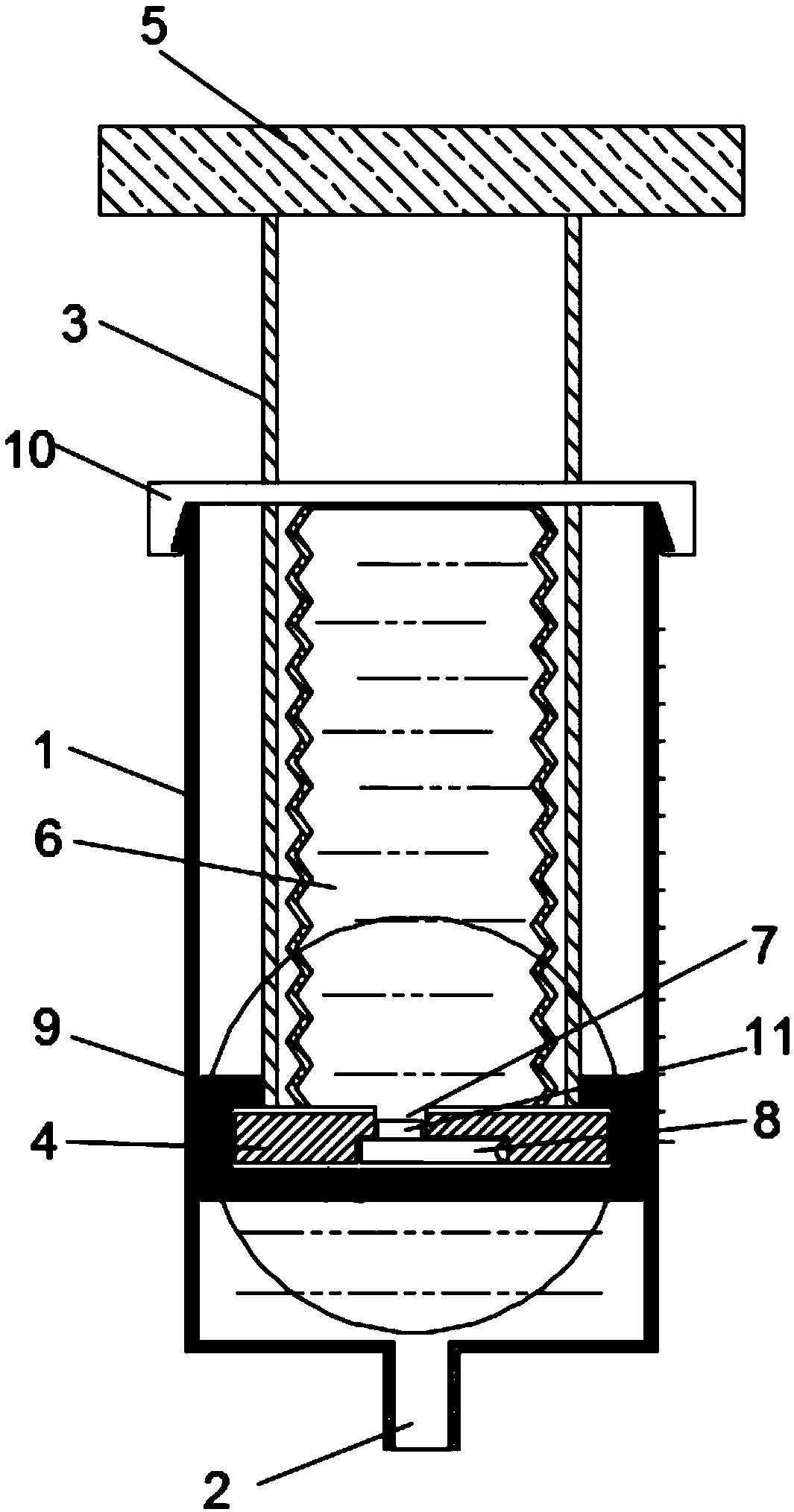
[0026] like figure 1 As shown, the present embodiment provides a syringe, which includes a syringe 1 and a needle connecting portion 2 arranged at the end of the syringe 1. A piston assembly is arranged inside the syringe 1, and the piston assembly includes a hollow push rod 3, which is pushed The end of the rod 3 close to the needle connection part 2 is provided with a piston plate 4, the end of the push rod 3 away from the needle connection part 2 is provided with a push handle 5, the push handle 5 is located outside the syringe 1, and the inside of the push rod 3 is provided with a liquid storage The cylinder 6, the opening end of the liquid storage cylinder 6 is fixedly connected with the piston plate 4, the piston plate 4 is provided with a through hole 7, and the end of the through hole 7 near the needle connection part 2 is provided with a one-way valve 8, and the piston plate 4 is covered outside A rubber sleeve 9 is provided, the rubber sleeve 9 below the one-way valv...

Embodiment 2

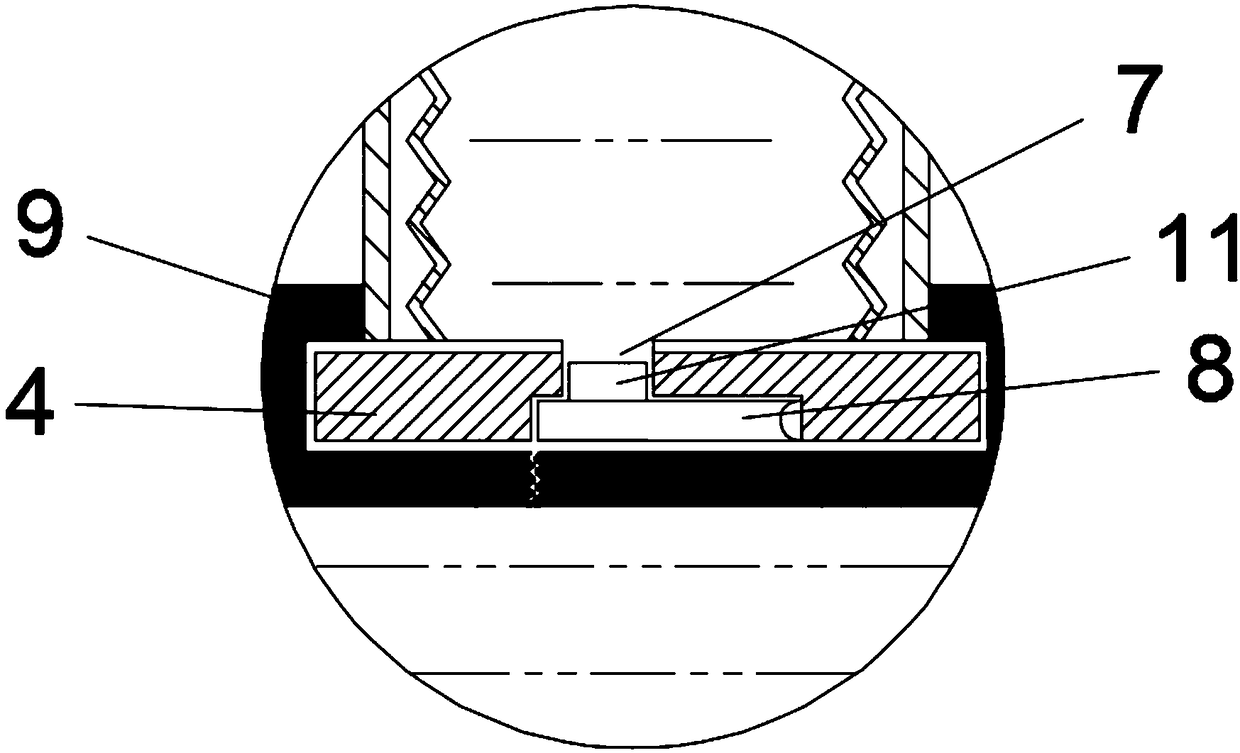
[0030] like figure 2 As shown, this embodiment is further optimized on the basis of Embodiment 1. Specifically, the one-way valve 8 includes a valve plate, which is hinged to the bottom of the piston plate 4. When the valve plate rotates upward, it is blocked by the bottom of the piston plate 4, so It can only be rotated downwards to play the role of guiding check valve 8.

[0031] As a preferred manner, a blocking block 11 extending into the through hole 7 is provided on the top of the valve plate, and the blocking block 11 is provided to further prevent the liquid inside the liquid storage cylinder 6 from leaking.

[0032] As a preferred method, the slit is U-shaped. Specifically, the U-shaped bend corresponds to the hinged end of the valve plate, and the U-shaped opening corresponds to the movable end of the valve plate. The U-shaped slit is set so that the rubber The bottom of the sleeve 9 can form a hinged rubber part that rotates around the U-shaped bend to adapt to th...

Embodiment 3

[0035] like figure 1 and figure 2 As shown, this embodiment is further optimized on the basis of Embodiment 2. Specifically, there are two strip-shaped through grooves symmetrical to the central axis of the push rod 3 on the side wall of the push rod 3, and the baffle plate 10 runs through the two The strip-shaped through groove is clamped with the end of the injection barrel 1. The strip-shaped through groove can guide the up and down movement of the push rod 3, so that the push rod 3 can move up and down freely, and the clamped baffle 10 is set to make the baffle 10 The liquid storage bottle can be squeezed, and at the same time, the push rod 3, the baffle plate 10 and the syringe 1 can be disassembled conveniently.

[0036] In the syringe of the present invention, when it is in the initial state, that is, when it is not in use after the manufacture is completed, the rubber sleeve 9 should be in contact with the bottom of the injection cylinder 1, so that the one-way valve...


PUM


Abstract

The invention discloses an injector, and belongs to the technical field of medical instruments. The injector comprises a syringe and a syringe needle connecting part arranged at the end of the syringe. A piston assembly is arranged in the syringe, and comprises a hollow push rod, a piston plate is arranged at the end, close to the syringe needle connecting part, of the push rod, a liquid storage barrel is arranged in the push rod, the open end of the liquid storage barrel is fixedly connected with the piston plate, and a through hole penetrates through the piston plate. A one-way valve is arranged at the end, close to the syringe needle connecting part, of the through hole, the piston plate is sleeved with a rubber sleeve, a cutting joint penetrates through the rubber sleeve below the one-way valve, and a baffle for extruding a liquid storage bottle is arranged at the end, away from the syringe needle connecting part, of the syringe. According to the injector, liquid medicine is storedin the push rod, the push rod is pulled to complete liquid medicine loading work during use, the advantages of being fast in liquid medicine loading, preventing a syringe needle from being contaminated when passing through a medicine bottle and being easy and convenient to operate are achieved, the medicine bottle can be prevented from being abandoned all around, and influence on the environmentis avoided.

Description

technical field [0001] The present invention relates to the technical field of medical instruments, and more specifically relates to a syringe. Background technique [0002] A syringe is a common medical tool, and it is a common medical practice to use a syringe to perform various injection treatments after preparing a liquid medicine through a sealed bottle. [0003] Existing syringes and liquid medicine bottles are usually separated. During injection, the syringe is used to draw the liquid medicine from the liquid medicine bottle, and then the liquid medicine is injected into the body through the syringe. There are several problems in this injection method: 1. Bacteria The possibility of contaminating the liquid medicine increases. When the medicine bottle is not stored properly, external bacteria can easily contaminate the bottle cap. When the needle enters the bottle cap, it will come into contact with the bacteria, resulting in contamination of the medicine liquid. Ins...

Claims


Application Information

Patent Timeline
Patent Type & Authority Applications(China)
IPC IPC(8): A61M5/178A61M5/31
CPCA61M5/178A61M5/3129A61M2005/3114
Inventor 黄桂庭
Owner 黄桂庭
Why Eureka
Try Eureka