
PE (polyethylene) hot melt glue electric smelting casing

A technology of electric hot melt and hot melt adhesive, which is applied in the field of pipeline facilities, can solve the problems of low work efficiency, poor strength, running, dripping, and leaking at the joint, and achieve the effects of reducing labor intensity, improving connection strength, and labor-saving operation

Active Publication Date: 2019-02-22
大庆世杰建材有限公司
View PDF8 Cites 0 Cited by
  • Summary
  • Abstract
  • Description
  • Claims
  • Application Information

AI Technical Summary

Problems solved by technology

However, the currently used electrofusion fittings have obvious defects during use: 1. The strength of the existing electrofusion fittings after connection is poor. The joints of PE pipes are prone to running, dripping and leaking
2. The capacitance welding process includes two main processes of hot melting and cooling. After the hot melting process is completed, the two connected pipes need to be fixed by special clamps to prevent relative displacement between the electric fusion pipe fittings and the PE pipe (including Axial displacement and radial displacement), the fixing process must continue until the cooling process is completed, which undoubtedly reduces the work efficiency

Method used


Image

  • PE (polyethylene) hot melt glue electric smelting casing
  • PE (polyethylene) hot melt glue electric smelting casing
  • PE (polyethylene) hot melt glue electric smelting casing

Examples


Embodiment 1

[0021] This embodiment includes a joint body 1 , and a heating wire is arranged on the inner wall of the joint body 1 . The above are common structures in the prior art, and will not be repeated here.

[0022] The main innovations of the present invention are:

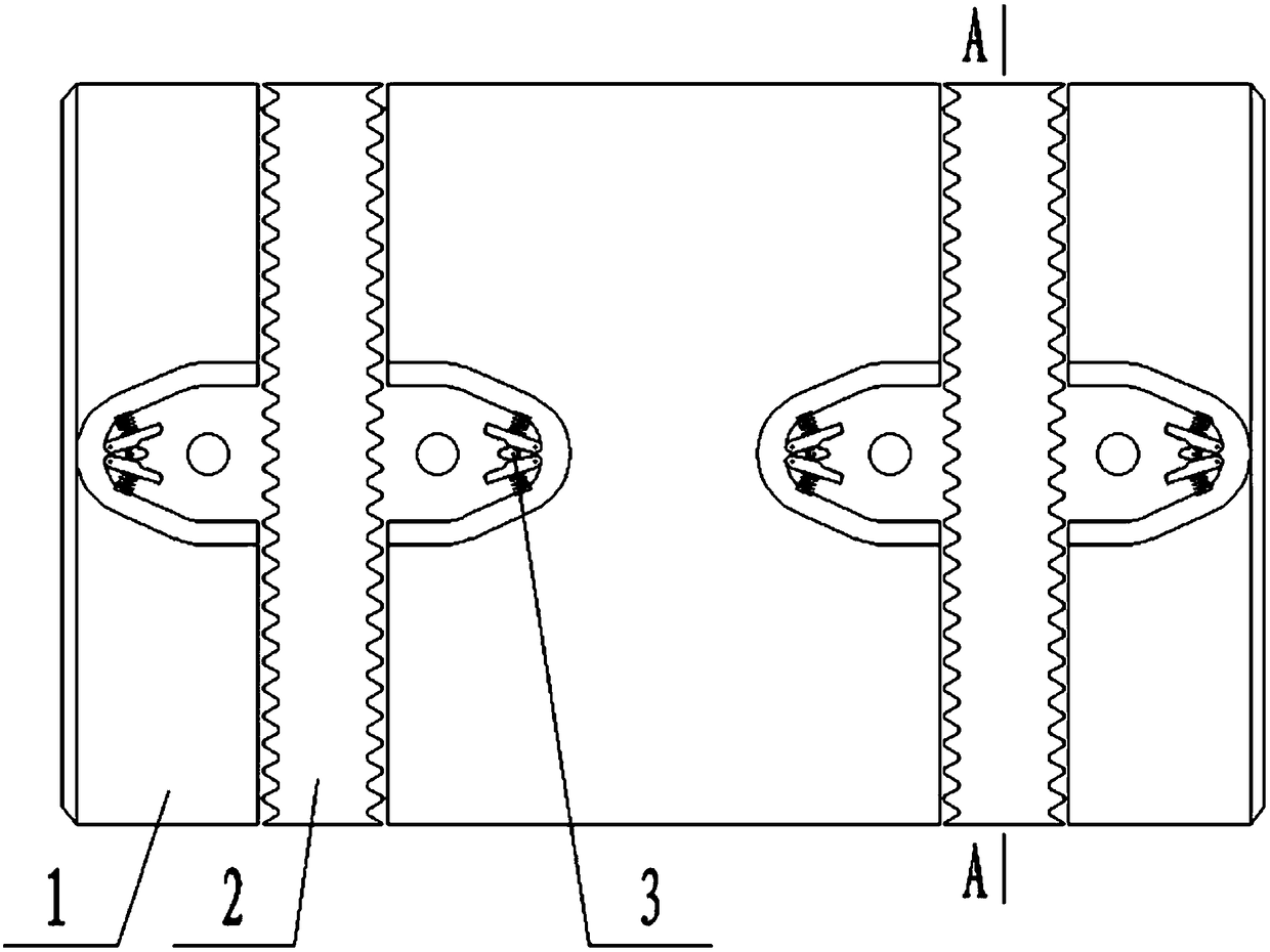
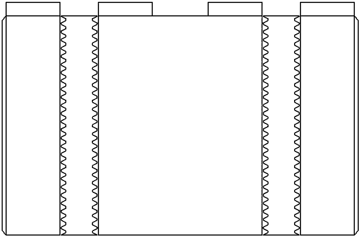
[0023] The two ends of the joint body 1 are each provided with a reinforcement and centralization device, through which the joint of the pipeline can be reinforced to improve the connection strength, and at the same time, the PE pipeline inside the joint body 1 is centered and centralized to improve the connection between the pipeline and the joint. The centering of the joint body 1 improves the quality of pipe connection.

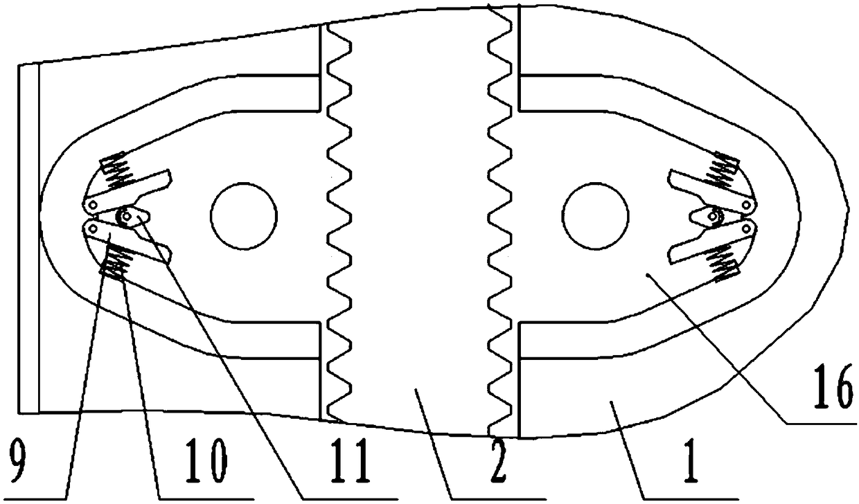
[0024] The structure of the reinforcing and centralizing device includes a ring gear 2, a locking pin 6 and a backstop mechanism 3. The ring gear 2 is installed in an annular groove outside the joint body 1, and the ring gear 2 can rotate around the annular groove. There are at least three lockin...

Embodiment 2

[0036] The difference between this embodiment and the first embodiment is that: as an alternative, the axis of the locking nail 6 is perpendicular to the guide slope 8 . Compared with Embodiment 1, when adopting the above-mentioned technical scheme, the head of the locking nail 6 only bears the frictional force applied by the guiding slope 8, and does not bear the overturning moment applied by the guiding slope 8. Therefore, this locking nail 6 The arrangement can not only make the locking nail 6 move more smoothly, but also effectively prevent the locking nail 6 from falling over.

[0037] The present invention is provided with a locking nail 6 structure, and the locking nail 6 can be pressed into the joint body 1 by rotating the ring gear 2. This structural form solves two problems: on the one hand, after the construction is completed, the upper end of the locking nail 6 is inserted On the joint body 1, the lower end of the locking nail 6 is inserted into the connected PE pi...


PUM


Abstract

The invention provides a PE (polyethylene) hot melt glue electric smelting casing, and relates to the technical field of pipeline facilities. The PE hot melt glue electric smelting casing comprises ajoint body; the inner wall of the joint body is provided with an electric heating wire; the PE hot melt glue electric smelting casing further comprises a driving device; the two ends of the joint bodyare each provided with a reinforcing and righting device; each reinforcing and righting device structurally comprises a gear ring, lock pins and non-return mechanisms; the gear rings are arranged ina ring groove in the outer side of the joint body; the side face of each gear ring is provided with gear teeth; the lock pins are arranged by at least three; all the lock pins are evenly inserted intothe bottom of the ring groove along the circumference; the upper end of each lock pin projects from the bottom of the ring groove; the lower end of each lock pin is of a conical structure; the tip ofeach conical structure is parallel and level with the inner wall of the joint body; and the inner wall of each gear ring is provided with guide oblique planes corresponding to the lock pins. According to the PE hot melt glue electric smelting casing, by installing the lock pins, not only can the connecting strength of pipelines be effectively improved, but also construction quality can be improved and construction efficiency is increased.

Description

Technical field: [0001] The invention relates to the technical field of pipeline facilities, in particular to a PE hot-melt adhesive electric heating sleeve. Background technique: [0002] The electric fusion pipe fitting is a commonly used PE pipe connector. Two PE pipes can be firmly connected together through the electric fusion pipe fitting. The working principle of the electric fusion pipe fitting is: the inner wall of the electric fusion pipe is The electric heating wire is connected to the electric fusion welding machine through the two electrodes exposed outside the electric fusion pipe fitting and energized. Through the heating effect of the electric heating wire, the hot melt glue inside the electric fusion pipe fitting is melted, and then bonded to the end of the PE pipe , to achieve the purpose of pipeline connection. However, the currently used electrofusion pipe fittings have obvious defects during use: 1. The strength of the existing electrofusion pipe fittin...

Claims


Application Information

Patent Timeline
Patent Type & Authority Applications(China)
IPC IPC(8): B29C65/42
CPCB29C65/42B29C66/80
Inventor 李艳杰李剑敬李平姜帆张正宝
Owner 大庆世杰建材有限公司
Learn More