Supercharge Your Innovation With Domain-Expert AI Agents!

Plug-in unit, plug-in connection, plug-in type steel pipe bundle and prefabrication and construction method of the plug-in type steel pipe bundle

A technology of steel pipe bundles and connecting units, which is applied in the direction of manufacturing tools, metal processing, metal processing equipment, etc., can solve the problems of long lap length, thick and dense steel bars, and the inability to use the strength of the web, etc., to achieve the effect of saving steel and simple structure

Inactive Publication Date: 2019-02-22
许仲群
View PDF0 Cites 0 Cited by
  • Summary
  • Abstract
  • Description
  • Claims
  • Application Information

AI Technical Summary

Problems solved by technology

[0002] Concrete is now poured into the steel pipe bundle as a shear wall or column. The steel pipe bundle is prefabricated in the factory, and the upper and lower steel pipe bundles are connected at the construction site. Since the separating webs of adjacent steel pipes are enclosed inside, the site cannot be directly connected by welding or bolts. Lap joints are usually used to insert steel bars. The vertical tension and pressure of the web need to be transmitted through the concrete and the steel bars. The steel bars need a long lap length, and the steel bars are thick and dense, which affects the pouring of the concrete. In this way, the web cannot be used for the lap joint. strength, unreasonable

Method used


Image

  • Plug-in unit, plug-in connection, plug-in type steel pipe bundle and prefabrication and construction method of the plug-in type steel pipe bundle
  • Plug-in unit, plug-in connection, plug-in type steel pipe bundle and prefabrication and construction method of the plug-in type steel pipe bundle
  • Plug-in unit, plug-in connection, plug-in type steel pipe bundle and prefabrication and construction method of the plug-in type steel pipe bundle

Examples


Embodiment 1

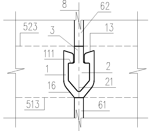
[0033] Such as figure 1 , 5 The plug-in units shown, including the buckle 1 and the plug 2, are all long linear shapes with a length greater than the cross section. In these two examples, a straight line is used; the middle of the buckle 1 has an accommodation space 11; there is an opening 12 along the length direction of the accommodation space 11, Its width is smaller than that of the accommodation space 11 , so that the plug 2 can be clamped in the accommodation space 11 and matched therewith.

[0034] In these two examples, the opening 12 is arranged on the top surface of the buckle 1, the first connected part 61 is connected to the bottom surface of the buckle 1, and the second connected part 62 is connected to the plug 2 through the opening 12, or connected to the handle 3 described below, The first and second connected parts 61 and 62 are tightly connected together through the plug 2 clamped in the accommodation space 11 to form a vertical 180° direct connection, which...

Embodiment 2

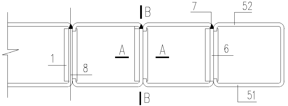
[0042] Such as Figure 2~4 , to adopt figure 1 The plug-in unit connects the steel pipe bundle assembly of the upper and lower steel pipe bundle webs. In this example, U-shaped steel units are arranged and connected in sequence to form steel pipes with cavities, which include a first flange 51, a second flange 52, and a web 6. The web 6 is a partition plate for adjacent steel pipes. . Connect the lower (steel tube bundle) web 61 and the upper (steel tube bundle) web 62 like the vertical 180° connection in Embodiment 1 to become a plug-in type steel tube bundle assembly, so that the web 6 can directly transmit the vertical Tension and compression can use the strength of the web.

[0043] Then connect the upper and lower first flanges 512, 511, connecting line 513; connect the upper and lower second flanges 522, 521, connecting line 523; then, pour concrete in the cavity of the steel pipe bundle, and other fillers can also be used. Such as grouting material, the filler squee...

Embodiment 3

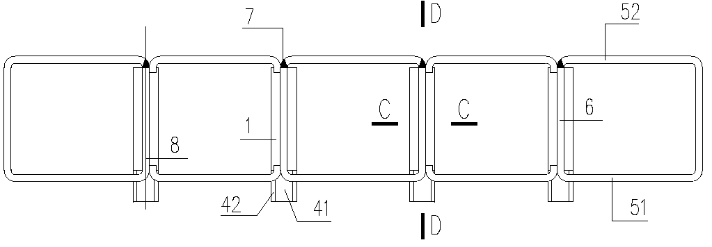
[0048] Such as Figure 6~8 for adoption Figure 5 The plug-in unit connects the steel pipe bundle assembly of the upper and lower steel pipe bundle webs. In this example, rectangular and plate steel units are arranged in turn to form a steel pipe bundle. The bottom surface of the mounting plate 4 is connected with the lower first flange 511, and the plug connection is according to the first embodiment Figure 4 It is explained that, after plugging, the mounting plate 4 is cut off from the outer surface of the flush first flange 51 , and the middle and upper surfaces 41 and 42 on both sides are connected to the upper first flange 512 . The positions of the connecting wires 513 and 523 are the same as that of the embodiment 2, which can be withdrawn and dismantled. The setting of the plug 2 and the buckle 1, the slit 7, the left and right symmetry axes of the section, and the application of structural glue are the same as the embodiment 2.

[0049] Because it is horizontally ...


PUM


Abstract

The invention provides a plug-in unit, plug-in connection, a plug-in type steel pipe bundle and prefabrication and construction methods of the plug-in type steel pipe bundle, and belongs to the fieldof steel structures. The plug-in unit includes a sleeving buckle and a plug, the sleeving buckle and the plug are of a long line shape, the middle of the sleeving buckle is provided with an accommodating space, an opening is formed in the length direction of the sleeving buckle, the width of the opening is less than that of the accommodating space, and the plug is arranged in the accommodating space in a clamped mode and matched with the accommodating space; a first connected piece is connected with the sleeving buckle, a second connected piece is connected with the plug or a handle through the opening; and webs of the upper and lower steel pipe bundles are connected by plug-in connection. The prefabrication method of the plug-in type steel pipe bundle includes the steps that webs of steelunits are connected with the sleeving buckle or a plug; the steel units are arranged as required, or the plug is firstly inserted into the sleeving buckle and then rearrangement is carried out; and the steel units are connected to form the steel pipe bundle. The field installation method of the plug-in type steel pipe bundle includes the steps that the sleeving buckle is heated; and then the plugis inserted. According to the plug-in unit, plug-in connection, the plug-in type steel pipe bundle and the prefabrication and construction methods of the plug-in type steel pipe bundle, the web strength can be utilized, rolled steel is saved, the structure is simple, and any position connection of the steel pipe bundle is adapted.

Description

technical field [0001] The invention belongs to the field of steel structures in the construction industry, and in particular relates to a steel pipe bundle connection. Background technique [0002] Concrete is now poured into the steel pipe bundle as a shear wall or column. The steel pipe bundle is prefabricated in the factory, and the upper and lower steel pipe bundles are connected at the construction site. Since the separating webs of adjacent steel pipes are enclosed inside, the site cannot be directly connected by welding or bolts. Lap joints are usually used to insert steel bars. The vertical tension and pressure of the web need to be transmitted through the concrete and the steel bars. The steel bars need a long lap length, and the steel bars are thick and dense, which affects the pouring of the concrete. In this way, the web cannot be used for the lap joint. The intensity is unreasonable. Contents of the invention [0003] The invention adopts the plug-in connect...

Claims


Application Information

Patent Timeline
IPC IPC(8): E04C5/02E04C5/16E04B2/58E04G21/14B23P19/00
CPCE04C5/02B23P19/00E04B2/58E04C5/162E04G21/14
Inventor 许仲群
Owner 许仲群
Features
  • R&D
  • Intellectual Property
  • Life Sciences
  • Materials
  • Tech Scout
  • Unparalleled Data Quality
  • Higher Quality Content
  • 60% Fewer Hallucinations
Learn More