Drum gear coupling for ESP finishing mill
A crown-shaped tooth and finishing mill technology, which is applied to the driving device, coupling, and metal rolling of metal rolling mills, and can solve the problem of fast wear on the tooth surface of sliding pinion gears, frequent axial expansion and contraction, and aggravated tooth surface wear and other issues to achieve the effect of reducing labor intensity, ensuring high efficiency and improving product quality
- Summary
- Abstract
- Description
- Claims
- Application Information
AI Technical Summary
Problems solved by technology
Method used
Image
Examples
Embodiment 1
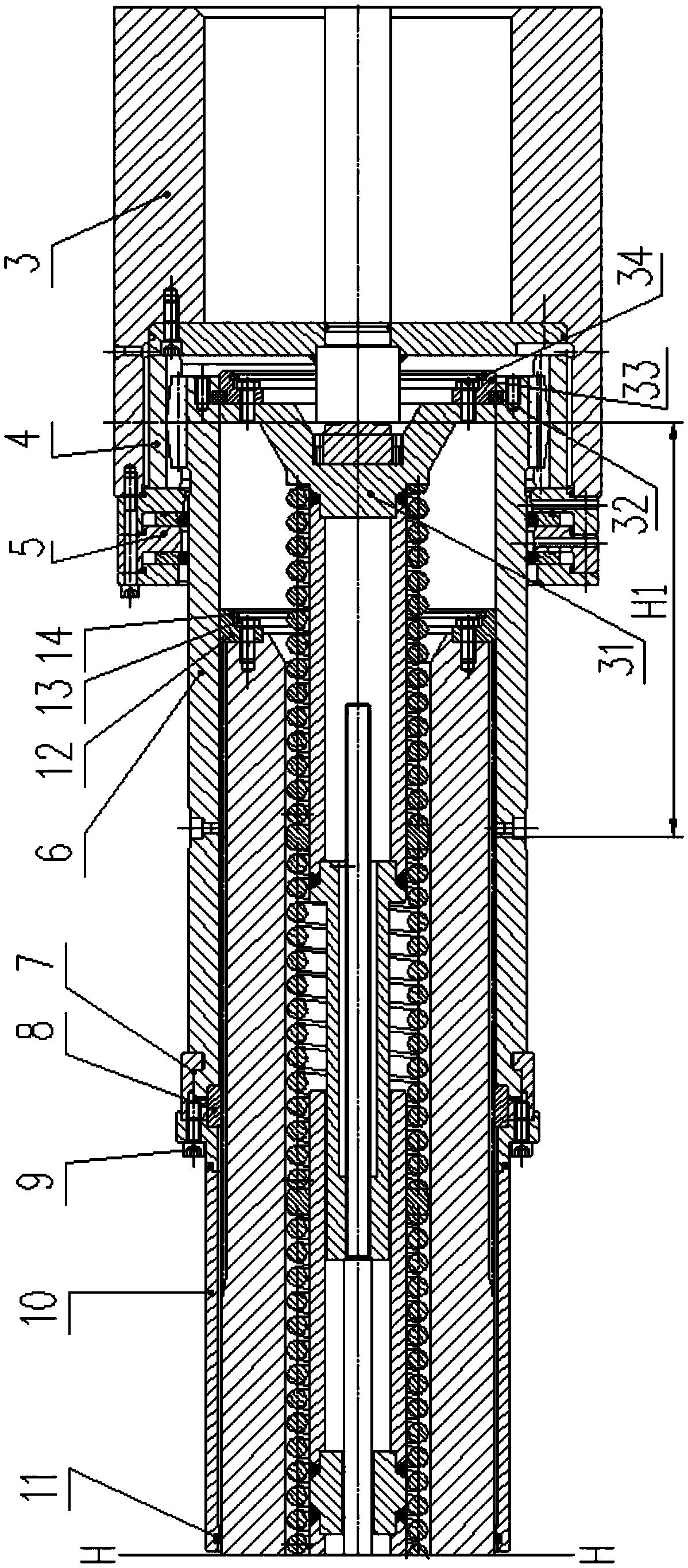
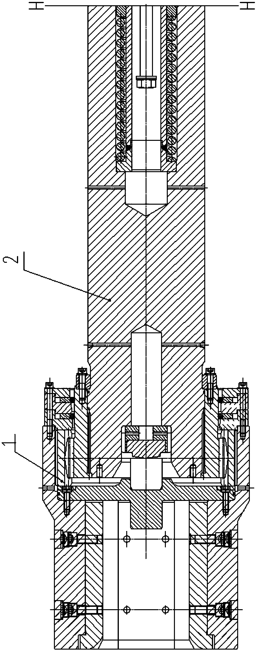
[0024] like figure 1 , figure 2 , image 3 As shown, a drum-shaped gear joint shaft of an ESP finishing mill of the present invention includes a roll end assembly 1, a reducer end shaft sleeve 3, a reducer end transition ring gear 4, and it also includes a spline shaft 2, a reducer end external gear Shaft sleeve 6, protective cover 10, seal assembly 5 at the end of the reducer; the protective cover 10 is set outside the spline shaft 2, and the left end of the outer gear sleeve 6 at the end of the reducer passes through the inner spline and the outer spline at the right end of the spline shaft 2 Its right end meshes with the internal teeth of the transition ring gear 4 at the reducer end through the external teeth, and the protective cover 10 is connected with the external gear sleeve 6 at the reducer end; the seal assembly 5 at the reducer end is installed on the reducer end sleeve 3 through bolts , and be set on the outer circle of the outer gear sleeve 6 at the end of th...
Embodiment 2
[0028] The drum-shaped gear joint shaft of the ESP finishing mill of the present invention also includes a first centering ring 8 and a split snap ring 7; the split snap ring 7 is arranged between the protective cover 10 and the outer gear sleeve 6 at the end of the reducer, and is stuck in the In the card groove of the outer circle of the outer gear sleeve 6 at the end of the reducer, the flange surface on the right side of the protective cover 10 is connected and fixed with the threaded hole of the split snap ring 7 through the screw 9, and the first centering ring 8 is fixed on the protective cover. 10. Split the space formed by the snap ring 7 and the spline shaft 2.
[0029] Wherein, the inner hole of the first centering ring 8 is sleeved on the outer circle of the outer spline of the spline shaft 2, and its outer circle is in contact with the left end seam of the outer gear sleeve 6 at the end of the reducer.
[0030] At the same time, the ESP drum-shaped toothed shaft o...
Embodiment 3
[0034] The drum gear joint shaft of the ESP finishing mill of the present invention also includes a seal 11; the seal 11 is arranged in the seal groove at the left end of the protective cover 10, and is sleeved on the outer circle of the spline shaft 2.
[0035] The seal 11 prevents external dust and the like from entering the spline pair, prolonging the service life of the connecting shaft.
PUM
 Abstract
Description
Claims
Application Information
 - R&D
- Intellectual Property
- Life Sciences
- Materials
- Tech Scout
- Unparalleled Data Quality
- Higher Quality Content
- 60% Fewer Hallucinations
Browse by: Latest US Patents, China's latest patents, Technical Efficacy Thesaurus, Application Domain, Technology Topic, Popular Technical Reports.
© 2025 PatSnap. All rights reserved.Legal|Privacy policy|Modern Slavery Act Transparency Statement|Sitemap|About US| Contact US: help@patsnap.com


