
Dust-removal carbon drying device

A drying device and carbon black technology, applied in the direction of drying gas arrangement, drying, drying machine, etc., can solve the problems of poor drying effect of carbon black and difficulty in dust removal

Pending Publication Date: 2019-02-22
攀枝花宝恒新材料科技有限公司
View PDF11 Cites 5 Cited by
  • Summary
  • Abstract
  • Description
  • Claims
  • Application Information

AI Technical Summary

Problems solved by technology

[0005] The present invention aims to provide a carbon black drying device for dust removal to solve the above-mentioned technical problems of poor carbon black drying effect and difficult dust removal in the prior art

Method used


Image

  • Dust-removal carbon drying device
  • Dust-removal carbon drying device
  • Dust-removal carbon drying device

Examples


Embodiment 1

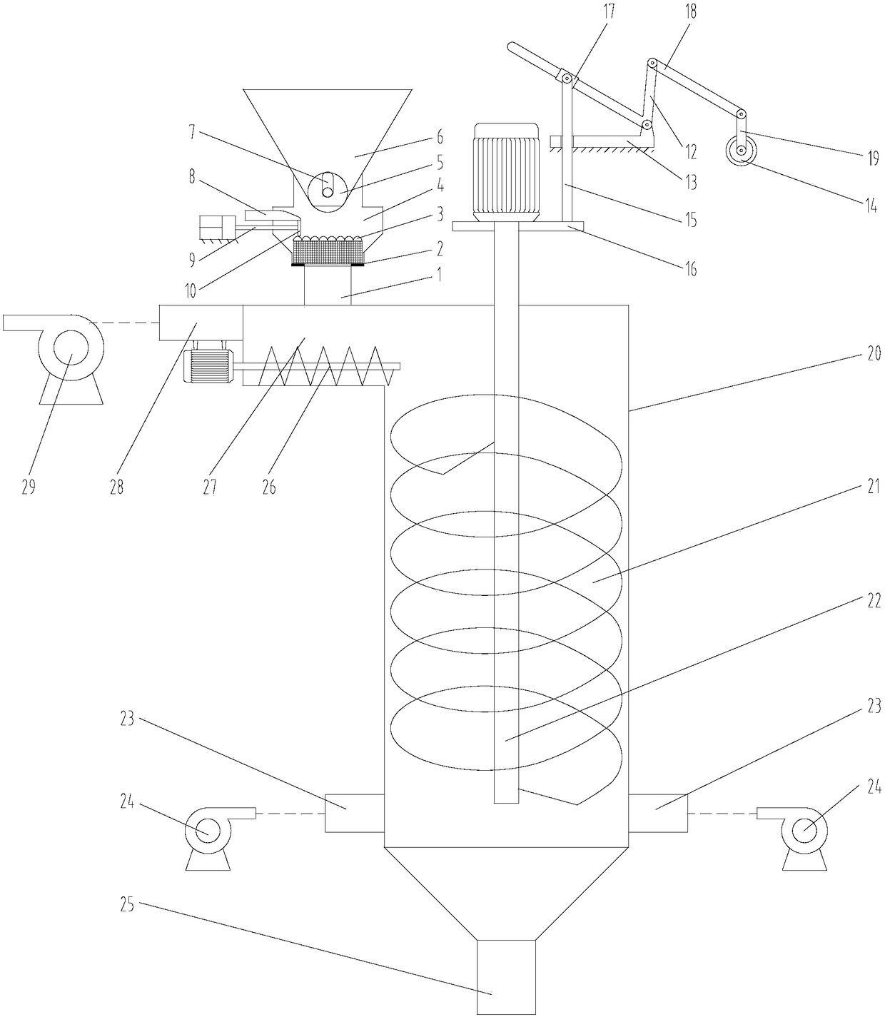
[0037] Such as figure 1 , figure 2 As shown, the present invention provides a dedusting carbon black drying device, including a vertical cylinder 20, the top of the cylinder 20 is closed; the upper part of the cylinder 20 is connected with a feed port 27, the free end of the feed port 27 An exhaust port 28 is connected; the upper part of the feed port 27 is connected with a feed assembly; the cylinder 20 is coaxially pierced with a rotating shaft 22, the upper end of the rotating shaft 22 extends out of the cylinder 20, and is configured to drive it A rotating drive device; a spiral plate 21 is fixed on the outer circumference of the rotating shaft 22, and the outer edge of the spiral plate 21 is matched with the inner wall of the cylinder 20; the plate surface of the spiral plate 21 is evenly provided with a plurality of vent holes The upper part of the cylinder 20 is provided with a lifting shaft 22 and a lifting assembly of the driving device; the lower section of the cylind...

Embodiment 2

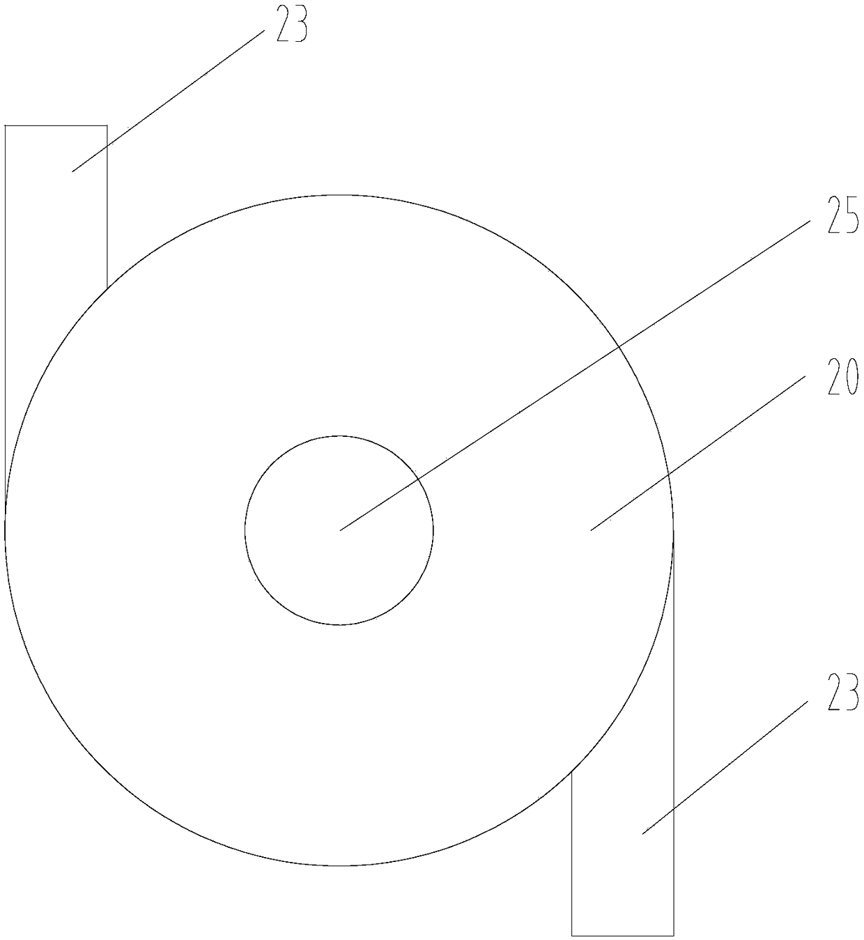
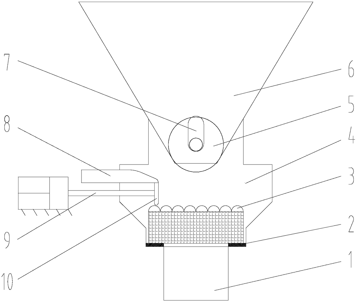
[0051] Such as Figure 1-Figure 5 As shown, the present invention provides a dedusting carbon black drying device, including a vertical cylinder 20, the top of the cylinder 20 is closed; the upper part of the cylinder 20 is connected with a feed port 27, the free end of the feed port 27 An exhaust port 28 is connected; the upper part of the feed port 27 is connected with a feed assembly; the cylinder 20 is coaxially pierced with a rotating shaft 22, the upper end of the rotating shaft 22 extends out of the cylinder 20, and is configured to drive it Rotating driving equipment; a spiral plate 21 is fixed on the outer circumference of the rotating shaft 22, and the outer edge of the spiral plate 21 is matched with the inner wall of the cylinder 20; the plate surface of the spiral plate 21 is evenly provided with a plurality of ventilation holes The upper part of the barrel 20 is provided with a lifting shaft 22 and a lifting assembly of the driving device; the lower section of the...


PUM


Abstract

The invention relates to the field of carbon black producing processing equipment, and discloses a dust-removal carbon drying device. The dust-removal carbon drying device comprises a vertical barrelbody, wherein the top of the barrel body is sealed; the upper part of the barrel body is connected with a charge hole; the free end of the charge hole is connected with an air exhaust hole; the upperpart of the charge hole is connected with a charge assembly; a rotary shaft is coaxially arranged in the barrel body in a penetrating mode; the upper end of the rotary shaft extends to the outside ofthe barrel body, and is equipped with drive equipment for driving the rotary shaft to rotate; a spiral plate is fixedly arranged at the periphery of the rotary shaft; the outer edge of the spiral plate is adaptive to the inner wall of the barrel body; a plurality of vent holes are uniformly formed in the plate surface of the spiral plate; a lifting-pulling rotary shaft and a lifting assembly of the drive equipment are arranged above the barrel body; the lower section of the barrel body is provided with a discharge hole; and the bottom of the barrel body is equipped with a hot air feeding-in hole. According to the dust-removal carbon drying device disclosed by the invention, carbon can be dried by many times, so that the carbon drying effect is especially obvious, the drying rate is also greatly increased, and the carbon drying process is shortened.

Description

Technical field [0001] The invention relates to the field of carbon black production and processing equipment, in particular to a carbon black drying device for removing dust. Background technique [0002] Carbon black, or carbon black, is an amorphous carbon. It is a light, loose, and extremely fine black powder with a very large specific surface area, ranging from 10 to 3000 m 2 / g, the specific gravity is 1.8-2.1. Carbon black is the product of incomplete combustion or thermal decomposition of carbonaceous materials (coal, natural gas, heavy oil, fuel oil, etc.) under conditions of insufficient air. Carbon black is the earliest nanomaterial developed and applied by mankind. It can endow other materials or products with some special performance properties and has an irreplaceable role in many fields. Carbon black is distinguished by performance, including "reinforcing carbon black", "conductive carbon black", "wear-resistant carbon black" and so on. Carbon black can be used ...

Claims


Application Information

Patent Timeline
Patent Type & Authority Applications(China)
IPC IPC(8): F26B17/22F26B21/00B07B4/02
CPCF26B17/22F26B21/004B07B4/02
Inventor 张军
Owner 攀枝花宝恒新材料科技有限公司
Learn More