Air knife and drying device using the air knife

An air-knife and drying-based technology, applied in the field of drying devices and air-knives, can solve the problems of affecting the drying effect, water droplets gathering and dripping on the air-knife device, secondary pollution, etc., so as to prolong the action time of wind and avoid secondary pollution. , the effect of extending the horizontal stroke

Active Publication Date: 2020-08-11
WUHAN CHINA STAR OPTOELECTRONICS TECH CO LTD
View PDF10 Cites 0 Cited by
  • Summary
  • Abstract
  • Description
  • Claims
  • Application Information

AI Technical Summary

Problems solved by technology

The existing air knife drying device uses fast high-pressure slit airflow to blow off water stains at one time, which has the following disadvantages: (1) The wind force has a short time to act, which cannot guarantee a good one-time drying effect, and is prone to occasional poor drying. Now, follow-up heating is often used Secondary drying method, high equipment cost; (2) The water stain on the surface of the substrate to be dried is suddenly subjected to high pressure and is easy to splash, which may easily cause water droplets to gather and drip on the air knife device, causing secondary pollution and affecting the drying effect

Method used


Image

  • Air knife and drying device using the air knife
  • Air knife and drying device using the air knife
  • Air knife and drying device using the air knife

Examples


Embodiment Construction

[0030] The specific implementation of the air knife provided by the present invention and the drying device using the air knife will be described in detail below in conjunction with the accompanying drawings.

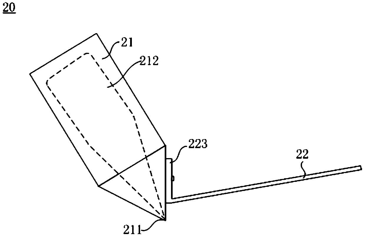
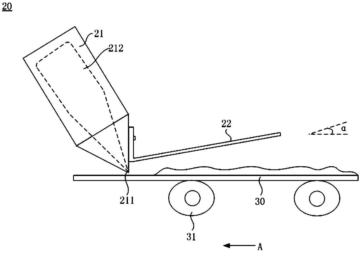
[0031] figure 2 It is a side view structural schematic diagram of an embodiment of the air knife of the present invention, image 3 It is a schematic side view of the working state of the air knife of the present invention, Figure 4 It is a top view structure schematic diagram of the working state of the air knife of the present invention. see figure 2 , image 3 and Figure 4 , The air knife 20 of the present invention includes a main air knife 21 and a deflector 22 .

[0032] The main air knife 21 is used to deliver a drying gas to a substrate 30 to be dried. Specifically, the main air knife 21 has an air outlet 211 , the air outlet 211 faces the substrate 30 to be dried, and the drying gas is blown toward the substrate 30 to be dried from the outlet 211 . T...


PUM


Abstract

An air knife (20) and a drying apparatus (100) using said air knife (20). A deflector (22) is provided on a side wall of a main air knife (21), the deflector (22) having an obstructing effect on a drying gas, extending a horizontal path of the drying gas, thereby extending the length of time of wind action of the drying gas, improving a drying effect thereof. The deflector (22) is also capable of having an obstructing effect on water droplets spraying up from a surface of a substrate to be dried (30) in response to high pressure, thus avoiding the occurrence of secondary contamination and the impact thereof on the drying effect.

Description

technical field [0001] The invention relates to the field of display devices, in particular to an air knife and a drying device using the air knife. Background technique [0002] In the manufacturing process of each component of the display device, wet equipment (Wet) is often required. For example, the cleaning machine (Cleaner) is used for cleaning the surface of the glass substrate before coating to remove dirt such as particles (Particle) and organic matter; Form the desired pattern. [0003] Wet equipment generally consists of rollers, spray washing, brushing, and air knife drying, among which the air knife with drying function is an important quality assurance part of wet equipment. The substrate to be cleaned, such as a glass substrate, is conveyed on the conveying roller and sprayed with water or liquid medicine or lotion by the spraying mechanism to wash away the particles, organic dirt, photoresist, etc. on the surface of the substrate, and then use the air knife...

Claims


Application Information

Patent Timeline
Patent Type & Authority Patents(China)
IPC IPC(8): F26B21/00
CPCF26B21/004
Inventor 施杰
Owner WUHAN CHINA STAR OPTOELECTRONICS TECH CO LTD
Why Eureka
Try Eureka