Light well-free deep hole slot broaching blasting method

A technology of pulling slots and deep holes, applied in blasting, earthwork drilling, ground mining, etc., can solve the problems of long cycle and high cost, and achieve the effect of reducing blasting costs and shortening the blasting cycle

Active Publication Date: 2019-02-22
SHAANXI METALLURGICAL DESIGN & RES INST CO LTD
View PDF4 Cites 4 Cited by
  • Summary
  • Abstract
  • Description
  • Claims
  • Application Information

AI Technical Summary

Problems solved by technology

In deep hole slotting blasting, patios are often used as the compensation space for blasting, resulting in high cost and long period of slotting blasting

Method used


Image

  • Light well-free deep hole slot broaching blasting method
  • Light well-free deep hole slot broaching blasting method
  • Light well-free deep hole slot broaching blasting method

Examples


Embodiment 1

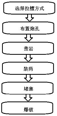
[0036] Such as Figure 1-3 A kind of blasting method without patio deep hole drawing groove shown, comprises the following steps:

[0037] Step 1: Select the slotting method

[0038] The slotting area in the stope adopts regular polygon hole layout;

[0039] Step 2: Arranging the blast holes

[0040] The blast hole adopts dense layout, and there are 4 charge blast holes in the slot blasting blast hole encryption area, 3 empty holes without charge, and 9 charge blast holes are arranged in two layers around the empty holes;

[0041] Step 3: Rock Drilling

[0042] For the blast hole arranged in step 2, the hole diameter of the charge blast hole is 90-130mm, and the hole diameter is 230-270mm for rock drilling;

[0043] Step 4: Charge

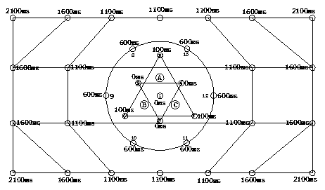
[0044] Charge the blast hole drilled in step 3. The charge structure is non-coupling charge, and the explosives with different detonation delays in the blast hole are all placed with a detonating charge bag;

[0045] Step Five: Blocking

[0...

Embodiment 2

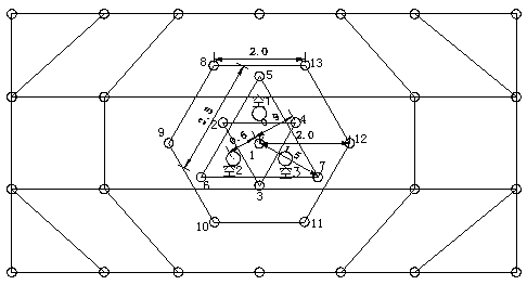
[0051] Such as figure 2 The shown one kind of blasting method of deep hole slotting without patio is different from the first embodiment in that: the specific way of the encryption arrangement in the step 2 is: the 4 holes in the blast hole densification area of ​​the slotting blasting There are three charge holes, one of which is located in the center of the groove area, and the remaining three charge holes and three empty holes are arranged in the form of an equilateral triangle; The three charge holes are arranged in an array on a concentric circle centered on the center hole in the slotting area. Three charge holes are arranged in the inner layer and six charge holes are arranged in the outer layer.

[0052] Preferably, the three empty holes are respectively arranged on the vertical bisector of the line connecting two adjacent charge blastholes of the three charge blastholes in the densified area of ​​the slot blasting blastholes arranged in an equilateral triangle; The ...

Embodiment 3

[0056] Such as figure 2 The shown one kind of blasting method of deep hole slotting without patio differs from Embodiment 2 in that: the three charge blast holes and slotting arranged in an equilateral triangle in the blast hole densification area of ​​the slotting blasting The center distance of the charge hole in the center of the area is 0.9m, and the center distance between the three empty holes and the charge hole in the center of the grooved area is 0.7m; the radius of the two concentric circles is 1.5m and 2m respectively.

[0057] Preferably, the linear distance between two adjacent charge holes on the circle with a radius of 2m is 2m.

[0058] The technical scheme of the invention not only saves the blasting cost, but also has better blasting effect.


PUM


Abstract

The invention belongs to the technical field of underground mine blasting and in particular relates to a light well-free deep hole slot broaching blasting method. Through six steps of selecting a slotbroaching mode, arranging a blasthole, drilling rocks, charging powder, blocking and blasting, a blasting method of slot broaching blasting is carried out directly by means of a compensation space provided by a large diameter empty hole without tunneling a light well in a stope by adopting a large diameter deep hole blasting post mining filling mining method, so that the blasting cost is loweredand the blasting period is shortened.

Description

technical field [0001] The invention belongs to the technical field of underground mine blasting, and in particular relates to a deep-hole slotting blasting method without a patio. Background technique [0002] Blasting is one of the key links in mining operations. The quality of blasting directly affects the ore recovery rate, dilution rate and ore lumpiness after blasting. The blasting in the large-diameter deep hole blasting followed by filling mining method is divided into slot blasting and side collapse blasting, and slot blasting is the first blasting area in the blasting operation, and the space generated after the blasting is the subsequent blast hole The initiation of blasting provides a lateral free surface, and the blasting quality of the groove directly affects the effect of lateral avalanche. In deep hole slotting blasting, the patio is often used as a blasting compensation space, resulting in high cost and long period of slotting blasting. Contents of the in...

Claims


Application Information

Patent Timeline
Patent Type & Authority Applications(China)
IPC IPC(8): F42D3/04F42D1/00E21C41/16
CPCE21C41/16F42D1/00F42D3/04
Inventor 郭霆杨平伟黄晓毅马玄恒王刚陈晓博杨超群郑卫琳罗小新付碧峰卢星柯昌涛范予晨
Owner SHAANXI METALLURGICAL DESIGN & RES INST CO LTD
Why Eureka
Try Eureka