Impact test device

A technology of impact test and limit device, which is used in measuring devices, instruments, scientific instruments, etc., can solve problems such as the influence of multiple impacts cannot be ignored, the impact results are not very accurate, and the lack of a drop weight limit device. The effect of reducing uncertainty, improving stability, and improving accuracy

Active Publication Date: 2019-02-22
CHANGAN UNIV
View PDF8 Cites 20 Cited by
  • Summary
  • Abstract
  • Description
  • Claims
  • Application Information

AI Technical Summary

Problems solved by technology

When these drop hammer impact testing machines are in the drop hammer impact test, after the drop hammer falls to hit the specimen, sometimes the drop hammer will rebound at a certain height and form a second or even three strikes on the specimen, which is not very good for the impact result. Accurate, with the continuous improvement of the precision requirements of the drop weight impact test, the influence of multiple impacts cannot be ignored more and more
For most drop weight impact testing machines, due to the lack of a drop weight limit device after the drop weight falls, it is easy to bring danger and bring uncertainty to the results

Method used


Image

  • Impact test device
  • Impact test device
  • Impact test device

Examples


Embodiment 1

[0038] Follow the above technical solutions, refer to Figure 1 to Figure 10 , This embodiment provides an axial compression loading device and method for impact testing, which is used for research on impact loads under axial compression conditions.

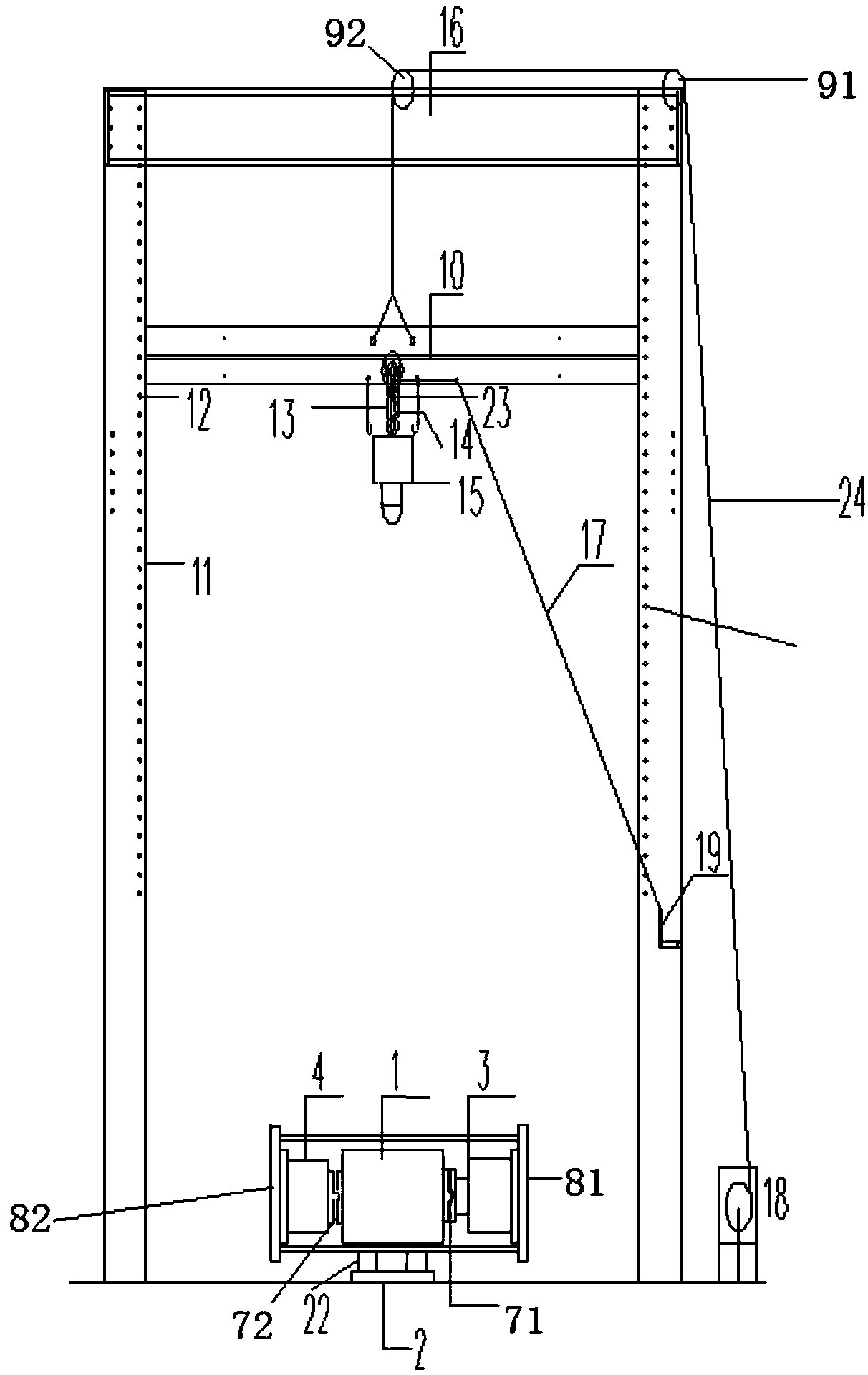
[0039] refer to figure 1 , an impact test device includes a lifting device, a clamp control system, a pressurizing device, a base and a drop weight 15.

[0040] Wherein, the lifting device includes a column 11 , a movable beam 10 , a first shaft wheel 91 , a second shaft wheel 92 , a steel strand 24 , a winch 18 and a screw rod 12 .

[0041]Two columns 11 are arranged vertically, and fixed beams 16 are fixed on the tops of the two columns 11, and the columns 11 are I-shaped. The column 11 is evenly provided with some bolt holes 25 along the vertical direction. The two ends of the movable beam 10 are all fixed on the column 11 by the screw rod 12. The movable beam 10 can move up and down inside the column 11. The beam 10 is fix...

Embodiment 2

[0058] refer to Figure 10 , the difference between this embodiment and embodiment 1 is that a protective limit device 28 is provided outside the test piece, refer to Figure 11 , the protection limiter 28 comprises a rectangular protective frame and a limiter fixed in the frame by a steel bar welded cross-section. The upper part of the protective frame is welded by four cross bars 39 and steel columns 38. The left and right sides of the lower part of the protective frame are obliquely welded with intersecting steel rods 30 and steel columns 38 .

[0059] The lower part is fixed with an inclined steel rod 30 for improving the stability of the frame, and the steel rod at the lower part of the frame is inclined outwards to improve the stability of the whole frame.

[0060] refer to Figure 12 , the limiting device includes a first memory metal 31, a second memory metal 32, a third memory metal 33, a fourth memory metal 34 and an electromagnet 35, wherein the first memory metal...


PUM


Abstract

The invention discloses an impact test device. The impact test device comprises a protecting-limiting device, wherein the protecting-limiting device is arranged outside a test piece and comprises a protecting framework and a limiting device, the protecting framework is formed by welding steel rods, and the limiting device is fixed in the protecting framework; and the limiting device comprises a first memory metal, a second memory metal, a third memory metal and a fourth memory metal which are sequentially fixedly connected, electromagnets are arranged at joints among the four memory metals. The safety of a test operator can be protected by virtue of the protecting device, and the falling position of a drop hammer can be effectively controlled by virtue of the limiting device, so that the secondary or repeated impact caused by the drop hammer to the test piece is avoided, and the accuracy of the test is increased; and furthermore, by virtue of a specific rest function of the memory metals, the damage caused by the impact force of the drop hammer to the protecting device can be reduced, the uncertainty in the test can be reduced, and the test precision is increased.

Description

technical field [0001] The invention belongs to the technical field of impact testing, and in particular relates to an impact testing device. Background technique [0002] When the traditional drop weight impact testing machine is used for testing, the drop weight is usually released from a certain test height, and the drop weight falls freely. When these drop hammer impact testing machines are in the drop hammer impact test, after the drop hammer falls to hit the specimen, sometimes the drop hammer will rebound at a certain height and form a second or even three strikes on the specimen, which is not very good for the impact result. Accurate, with the continuous improvement of the accuracy requirements of the drop weight impact test, the influence of multiple impacts cannot be ignored. For most drop weight impact testing machines, due to the lack of a drop weight limit device after the drop weight falls, it is easy to bring danger and bring uncertainty to the results. Con...

Claims


Application Information

Patent Timeline
Patent Type & Authority Applications(China)
IPC IPC(8): G01N3/303
CPCG01N3/303
Inventor 王步孙振月梁家琦毕铁川缪福军张诺亚
Owner CHANGAN UNIV
Why Eureka
Try Eureka