Adjustment method for fine adjustment of resistance value of thin film resistor, and thin film resistor

A thin film resistor, resistance adjustment technology, applied in the direction of fine-tuning resistors, resistance film/resistance coating is tapered, non-adjustable metal resistors, etc., can solve the problem of heavy workload, etching accuracy, laser equipment accuracy limitations, Design value deviation and other problems, to achieve the effect of improving efficiency, avoiding the influence of resistor dimensional accuracy and equipment accuracy

Active Publication Date: 2019-02-22
珠海杰赛科技有限公司 +1
View PDF3 Cites 0 Cited by
  • Summary
  • Abstract
  • Description
  • Claims
  • Application Information

AI Technical Summary

Problems solved by technology

[0009] 1. Among the key parameters of adjusting the resistance, L1 and W1 are limited by the etching precision of the resistance size and the precision of the laser equipment. In practical applications, due to the problem of graphic deviation and laser alignment deviation, there is a deviation between L1 and W1 and the design value. Finally, the adjusted resistance value does not match the expected problem;
[0010] 2. The above-mentioned laser adjustment resistance process has a slow response speed, and it is necessary to make temporary documents according to the actual resistance value after molding, which cannot be pre-designed, resulting in production stagnation;
[0014] 2. L-shaped laser cutting is used for adjustment, and the response speed is slow. It is necessary to measure the actual resistance value after forming, and then make a file, and it is impossible to make a laser file in advance;
[0015] 3. L-shaped laser cutting is used for adjustment, which is not suitable for mass production. Each resistor size and resistance value needs to use a separate file, which has a large workload and low efficiency

Method used


Image

  • Adjustment method for fine adjustment of resistance value of thin film resistor, and thin film resistor
  • Adjustment method for fine adjustment of resistance value of thin film resistor, and thin film resistor
  • Adjustment method for fine adjustment of resistance value of thin film resistor, and thin film resistor

Examples


Embodiment Construction

[0044] The present invention will be described in detail below with reference to the accompanying drawings and examples. It should be noted that in the case of no conflict, the following embodiments and the features in the embodiments can be combined with each other.

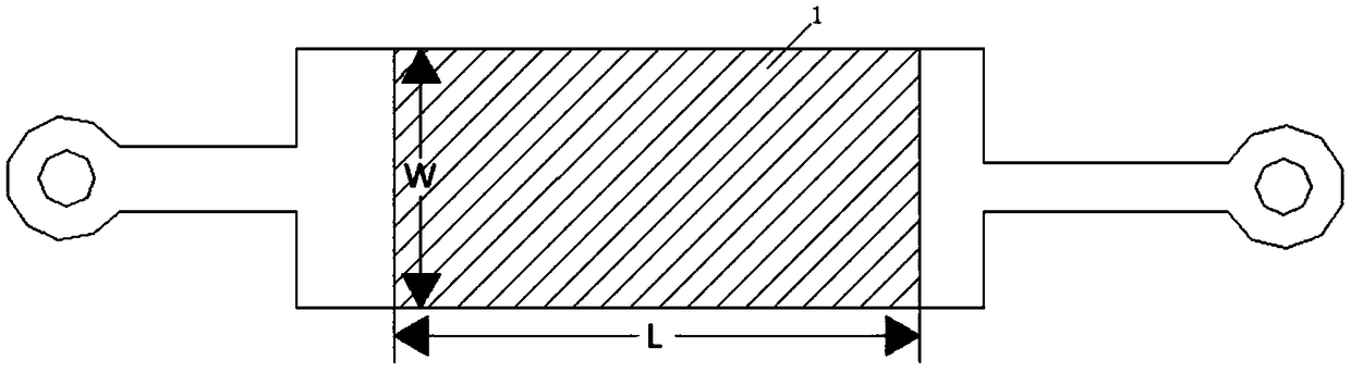
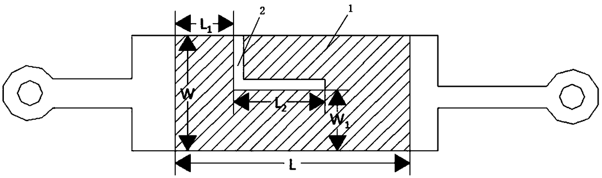
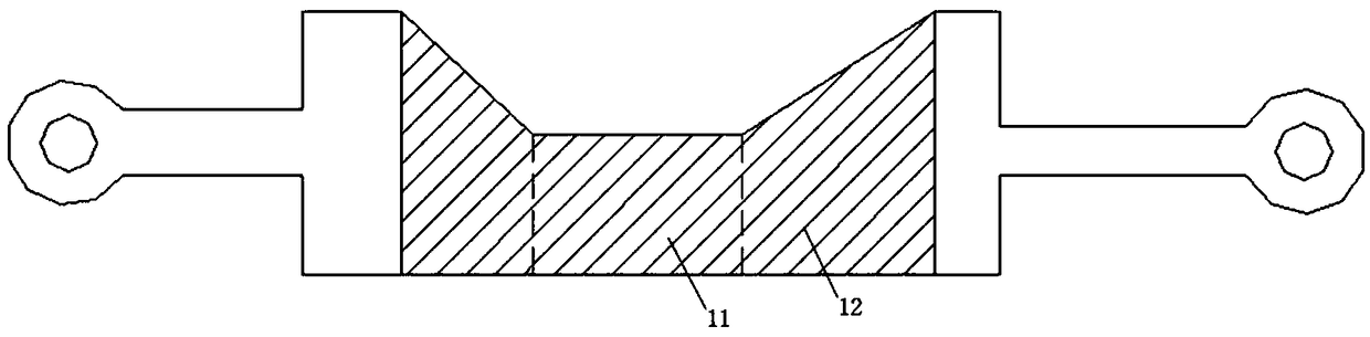
[0045] An adjustment method for fine-tuning the resistance value of a thin-film resistor, said method comprising setting several resistance adjustment holes, light spots or plaques inside the thin-film resistor according to the resistance value to be adjusted, and the thin-film resistance after setting the resistance adjustment holes or spots is Resistor after resistance adjustment. The manner of setting several resistance adjustment holes or spots includes single or double resistance adjustment holes, light spots, erosion spots, or matrix type resistance adjustment holes, light spots, and erosion spots.

[0046] Among them, the number and diameter of resistance adjustment holes, light spots or plaques are obta...


PUM


Abstract

The invention discloses an adjustment method for fine adjustment of a resistance value of a thin film resistor, and the thin film resistor. The adjustment method is characterized by comprising the steps: a plurality of resistance adjustment holes or spots are arranged in the thin film resistor according to the resistance value, needing to be adjusted, of the resistor, and the thin film resistor provided with the resistance adjustment holes or spots is the resistor with the adjusted resistance value. Through the mode that the multiple holes or spots are arranged in the resistor, the problem that the adjusted resistance value is greatly different from the actual demand due to L-shaped laser cutting adjustment is avoided.

Description

technical field [0001] The invention belongs to the technical field of thin-film resistor production, and in particular relates to an adjustment method for fine-tuning the resistance value of the thin-film resistor and the thin-film resistor. Background technique [0002] Thin film resistors are high-end products in printed circuit boards. Through a series of complex processes such as optical imaging and potion etching, while making circuits, a certain size of resistive film area is produced, and it has the same function as resistive components, saving Go to the SMT where the device is mounted, and it does not take up printed circuit board space. Such as figure 1 As shown, the schematic diagram of the thin film resistor 1 after molding, the calculation formula of the resistance value of the thin film resistor 1 is [0003] R=R 方 *L / W [0004] Among them, R is the resistance value of the resistor, R square is the square resistance of the thin film resistor, L is the lengt...

Claims


Application Information

Patent Timeline
Patent Type & Authority Applications(China)
IPC IPC(8): H01C7/20H01C7/00H01C17/235H01C17/242
CPCH01C7/00H01C7/20H01C17/22H01C17/235Y02P70/50
Inventor 林荣富关志锋李超谋
Owner 珠海杰赛科技有限公司
Why Eureka
Try Eureka