Filter type slot antenna

A slot antenna and slot technology, applied in the field of communication, can solve the problems of large size and large return loss of filter-type slot antennas, and achieve the effects of small size, enhanced electromagnetic coupling, and reduced return loss

Inactive Publication Date: 2019-02-22
ZHONGXIANGBOQIAN INFORMATION TECH CO LTD
View PDF6 Cites 4 Cited by
  • Summary
  • Abstract
  • Description
  • Claims
  • Application Information

AI Technical Summary

Problems solved by technology

[0004] In view of this, the purpose of the present invention is to overcome the deficiencies of the prior art and provide a filter-type slot antenna. In o

Method used


Image

  • Filter type slot antenna

Examples


Embodiment Construction

[0027] In order to make the purpose, technical solution and advantages of the present invention clearer, the technical solution of the present invention will be described in detail below. Apparently, the described embodiments are only some of the embodiments of the present invention, but not all of them. Based on the embodiments of the present invention, all other implementations obtained by persons of ordinary skill in the art without making creative efforts fall within the protection scope of the present invention.

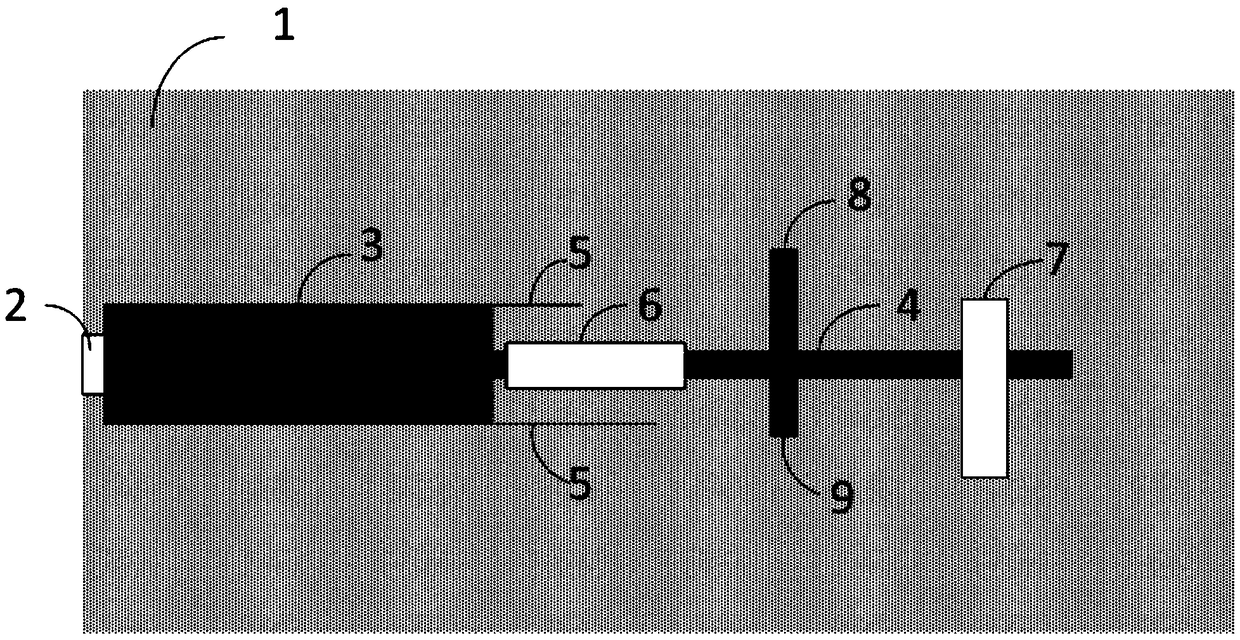
[0028] figure 1 It is a schematic structural diagram of a filtering slot antenna provided in Embodiment 1 of the present invention. Such as figure 1 As shown, a filter-type slot antenna provided in this embodiment includes: a dielectric plate 1, an input port 2, a microstrip line 3, a half-wavelength line resonator 4, an open stub, a defective ground structure 5 and a ground plane gap. Wherein, the input port 2 is disposed on the dielectric board 1, the micr...


PUM


Abstract

The invention relates to a filter type slot antenna. The filter type slot antenna comprises a dielectric plate, an input port, a microstrip line, a half-wavelength line resonator, an open branch, anda slot between a defect grounding structure and a grounding plane; the input port is disposed on the dielectric plate, and the slot is divided a first sub-slot and a second sub-slot; the microstrip line is disposed on a bottom layer of the dielectric plate, and the resonant frequency is generated by the half-wavelength line resonator loaded on the second sub-slot to obtain a dual-band filtering characteristic; and the open branch is placed on the half-wavelength line resonator, and the response frequency of the input port is increased; the slot formed in the grounding plane is used to radiateelectromagnetic waves; and the defect grounding structure is loaded on the input port, which enhances the electromagnetic coupling of the input port. The filter type slot antenna formed by integratingthe half-wavelength line resonator and the antenna described above is used, so that the size of the filter type slot antenna is smaller when the impedance in the antenna band is matched, and the effect of reducing the return loss is achieved.

Description

technical field [0001] The invention relates to the field of communication technology, in particular to a filter type slot antenna. Background technique [0002] With the rapid development of science and technology, the development of science and technology has driven the development of wireless communication technology. People's requirements for wireless communication quality are getting higher and higher. Modern wireless communication systems are developing towards miniaturization. From the previous long external antenna to The current built-in antenna, wireless communication is developing towards intelligence. In order to make the size of the wireless communication system smaller and have good filtering characteristics, it is necessary to combine the antenna with the filtering unit, so that the filter antenna formed has better filtering characteristics. and radiation properties. [0003] In the existing filter antenna, the filter unit and the radiation unit are designed ...

Claims


Application Information

Patent Timeline
IPC IPC(8): H01Q1/38H01Q1/48H01Q1/50H01Q13/10
CPCH01Q1/38H01Q1/48H01Q1/50H01Q13/10
Inventor 曾庆生张跃进
Owner ZHONGXIANGBOQIAN INFORMATION TECH CO LTD
Why Eureka
Try Eureka