
Electric power meter fixing box and acquisition system thereof

A technology of a power meter and an acquisition system, which is applied to the field of a power meter fixing box and its acquisition system, can solve problems such as damage to the power meter, dust sticking to the power meter, and damage to the parts of the power meter.

Inactive Publication Date: 2019-02-22
彭世健
View PDF6 Cites 2 Cited by
  • Summary
  • Abstract
  • Description
  • Claims
  • Application Information

AI Technical Summary

Problems solved by technology

The existing electric meter container has the disadvantages of vibration during transportation, which may easily damage the internal parts of the electric meter, difficulty in fixing the electric meter during transportation and easy damage to the electric meter, and dust on the electric meter during transportation

Method used


Image

  • Electric power meter fixing box and acquisition system thereof
  • Electric power meter fixing box and acquisition system thereof

Examples


Embodiment 1

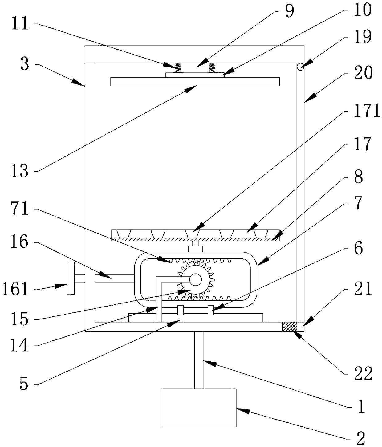
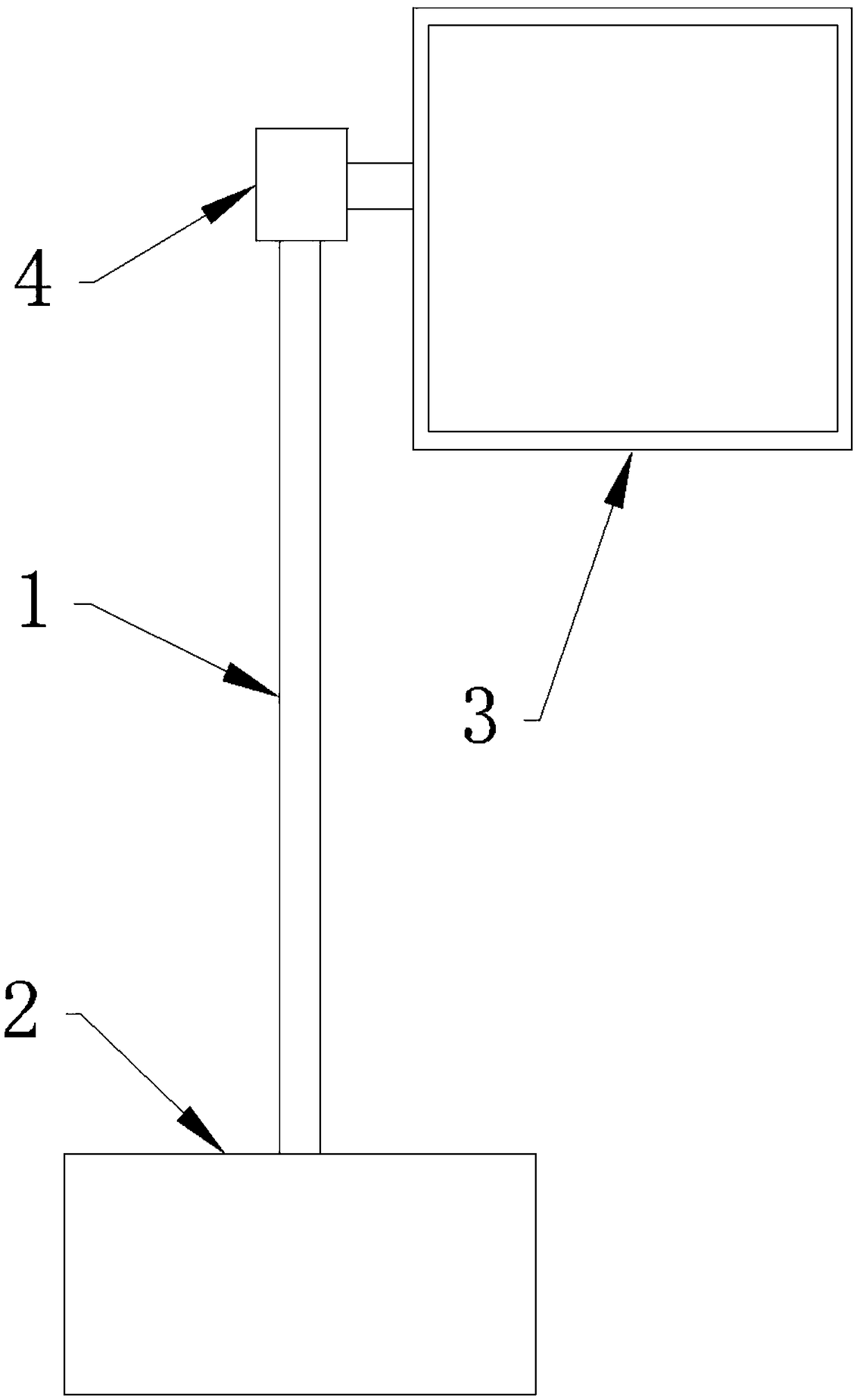
[0020] Such as Figure 1-2 As shown, this embodiment relates to an electric meter box, including a telescopic rod 1, a third motor 2 and a housing 3, the third motor 2 is arranged at the lower end of the telescopic rod 1, and the telescopic rod 1 is connected to the housing 3 through a rotating block 4. connection, a slide rail 5 is provided below the housing 3, and the slide rail 5 is slidably connected with a moving frame 7 through the first slider 6, and a pressing plate 8 is connected to the moving frame 7, and a movable rod 9 is arranged on the top of the housing 3, and the movable A limit block 10 is provided at the top of the rod, and the limit block 10 is connected to the top of the housing through a spring 11 , and a mounting plate 13 is fixedly connected to the bottom of the limit block 10 .

[0021] The upper and lower sides of the moving frame 7 are symmetrically provided with racks 71, and one side of the first slide block 6 is provided with a pole 14, and the pol...

Embodiment 2

[0026] A power meter collection system in a power meter box, including a system master station, a concentrator, a processor, a collector, and a power meter, where the power meter includes a water meter, an electric energy meter, a gas meter, and a heat meter, and the collector collects data from the power meter Each data is transmitted to the processor, the processor is connected to a concentrator by carrier wave, the concentrator is connected to a display through GPRS or Ethernet, and the concentrator is also connected to the system master station through Ethernet;

[0027] Among them, the water meter and gas meter are connected to the collector through the M-BUS bus using the CJ / T 188-2004 protocol communication method, and the electric meter is connected to the collector through the RS-485 bus using the DL / T 645-2007 / 1997 protocol communication method. The meter is connected to the collector through the RS-485 bus using CJ / T 188-2004.

[0028] Use the data of each table to ...


PUM


Abstract

The invention discloses an electric power meter fixing box. The electric power meter fixing box comprises a telescopic rod, a third motor and a casing; the third motor is disposed at a lower end of the telescopic rod, and the telescopic rod is connected to the casing through a rotating block; a slide rail is disposed on the bottom of the casing; the slide rail is slidably connected to a moving frame through first sliding blocks; the moving frame is connected to a pressing plate; a movable rod is disposed on the upper side of the casing; a limiting block is arranged on the top end of the movable rod; the limiting block is connected to the upper part of the casing through springs; and a mounting plate is fixedly connected to the lower part of the limiting block. The moving frame is arrangedin the casing of the electric power meter box, which facilitates movement of the electric power meter box; the whole electric power meter is fixed and limited through the springs and a rubber pad, which can buffer vibration and protect internal parts of the electric power meter from being damaged, and prevent the electric power meter from dust during transportation.

Description

technical field [0001] The invention relates to the technical field of electric meters, in particular to an electric meter fixing box and an acquisition system thereof. Background technique [0002] Power meters are power measurement and control equipment that provide solutions for power parameter measurement, power quality monitoring and analysis, and electrical equipment control. As an advanced intelligent and digital grid front-end acquisition component, power meters have been widely used in various control systems. System, SCADA system and energy management system, substation automation, community power monitoring, industrial automation, intelligent building, intelligent power distribution cabinet, switch cabinet and other equipment. In order to prevent electric shock, power meters are generally installed on walls or poles. Maintenance personnel need to use tools such as ladders to work in the air during the maintenance process, which poses a safety hazard. [0003] Pow...

Claims


Application Information

Patent Timeline
Patent Type & Authority Applications(China)
IPC IPC(8): H05K5/02G05B19/418
CPCG05B19/4183H05K5/0217Y02P90/02
Inventor 彭世健
Owner 彭世健
Learn More