Split type charging equipment of electric vehicle and working method thereof

A technology for electric vehicles and charging equipment, applied in the direction of electric vehicle charging technology, electric vehicles, charging stations, etc., can solve problems such as high investment costs, difficult unified management of private cars, hidden safety hazards, etc., to achieve mileage and convenient charging , reducing the effect of the process

Inactive Publication Date: 2019-02-26
侍雨
View PDF0 Cites 3 Cited by
  • Summary
  • Abstract
  • Description
  • Claims
  • Application Information

AI Technical Summary

Problems solved by technology

Subsequently, the development of electric vehicle charging stations has become inevitable, but under the current circumstances, the development of charging stations cannot match the development of electric vehicles, making it impossible for electric vehicles to enter the homes of ordinary people in the short term.
[0003] The establishment of a large-scale charging station requires the establishment of a dedicated charging network, which requires the transformation of the power grid. The investment cost is too high, and it is difficult to realize the application in the short term. Therefore, the number of concentrated charging stations is still very small, which makes it inconvenient to charge electric vehicles. Charging also has potential safety hazards; and private cars are difficult to manage in a unified manner, which cannot solve the problems of electric vehicle mileage and convenient charging

Method used


Image

  • Split type charging equipment of electric vehicle and working method thereof
  • Split type charging equipment of electric vehicle and working method thereof
  • Split type charging equipment of electric vehicle and working method thereof

Examples


Embodiment 1

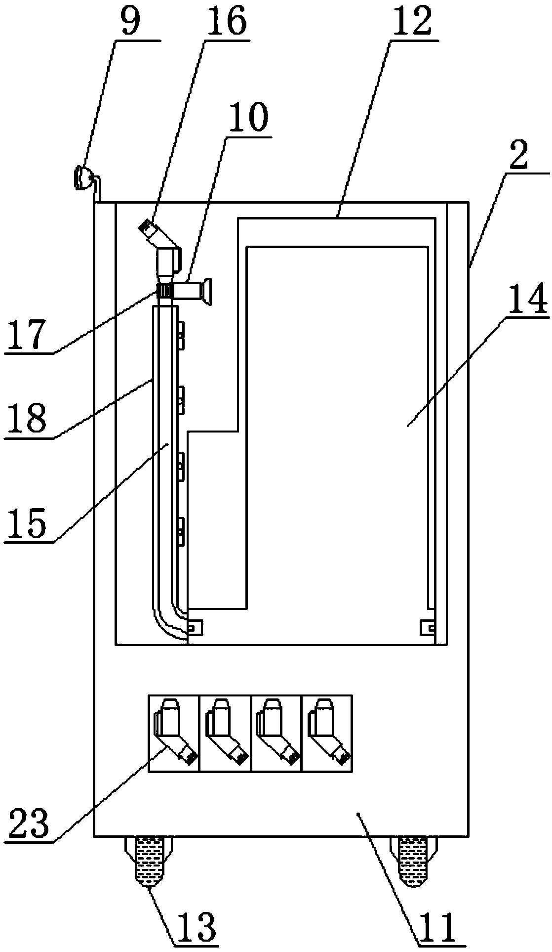
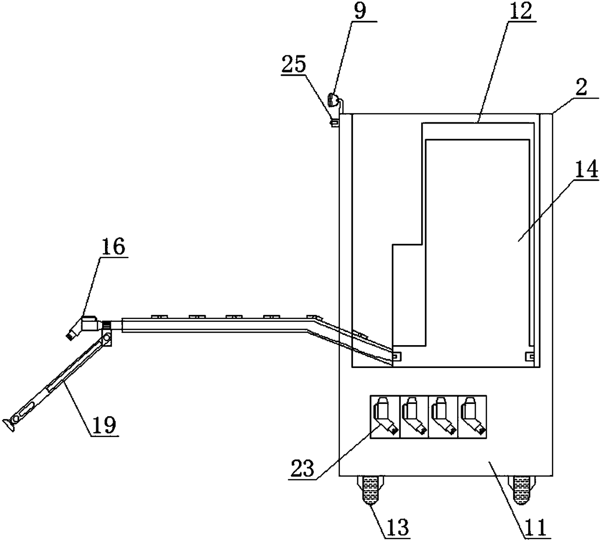
[0056] Such as figure 1 , 2 , 3, 4, 5, 6, a split type charging device for electric vehicles, including a charging station 1, a split mechanism 2 and a control mechanism 3. The control mechanism 3 includes a processor 4, a driving device 5, a positioning The device 6 and the navigation device 7, and the processor 4 are respectively connected with the driving device 5, the positioning device and the navigation device 7. The positioning device 6 is used to obtain the position information of the split mechanism 2 and send the position information to the processor 4, and the navigation device 7. Used to generate the moving route of the split mechanism 2 and send the moving route to the processor 4. The split mechanism 2 is parked in the charging station 1. The charging station 1 includes a first connecting device 8, the first connecting device 8 and the split mechanism 2 is connected to the input end of the battery 14, the split mechanism 2 includes a camera device 9, an opening dev...

Embodiment 2

[0065] Such as Figure 7 As shown, a working method of a split charging device for electric vehicles includes the following working steps:

[0066] a) The processor 4 receives the charging request sent by the user in real time, and the charging request includes the first location information of the electric vehicle and the license plate number of the electric vehicle;

[0067] b) The positioning device 6 obtains the second position information of the split mechanism 2 and sends the second position information to the processor 4. The processor 4 imports the first position information and the second position information into the navigation device 7, and the navigation device 7 generates the second position information. 2. The first moving route from the position information to the first position information and sending the first moving route to the processor 4;

[0068] c) The processor 4 outputs the first movement signal to the driving device 5, and the driving device 5 drives the mob...

Embodiment 3

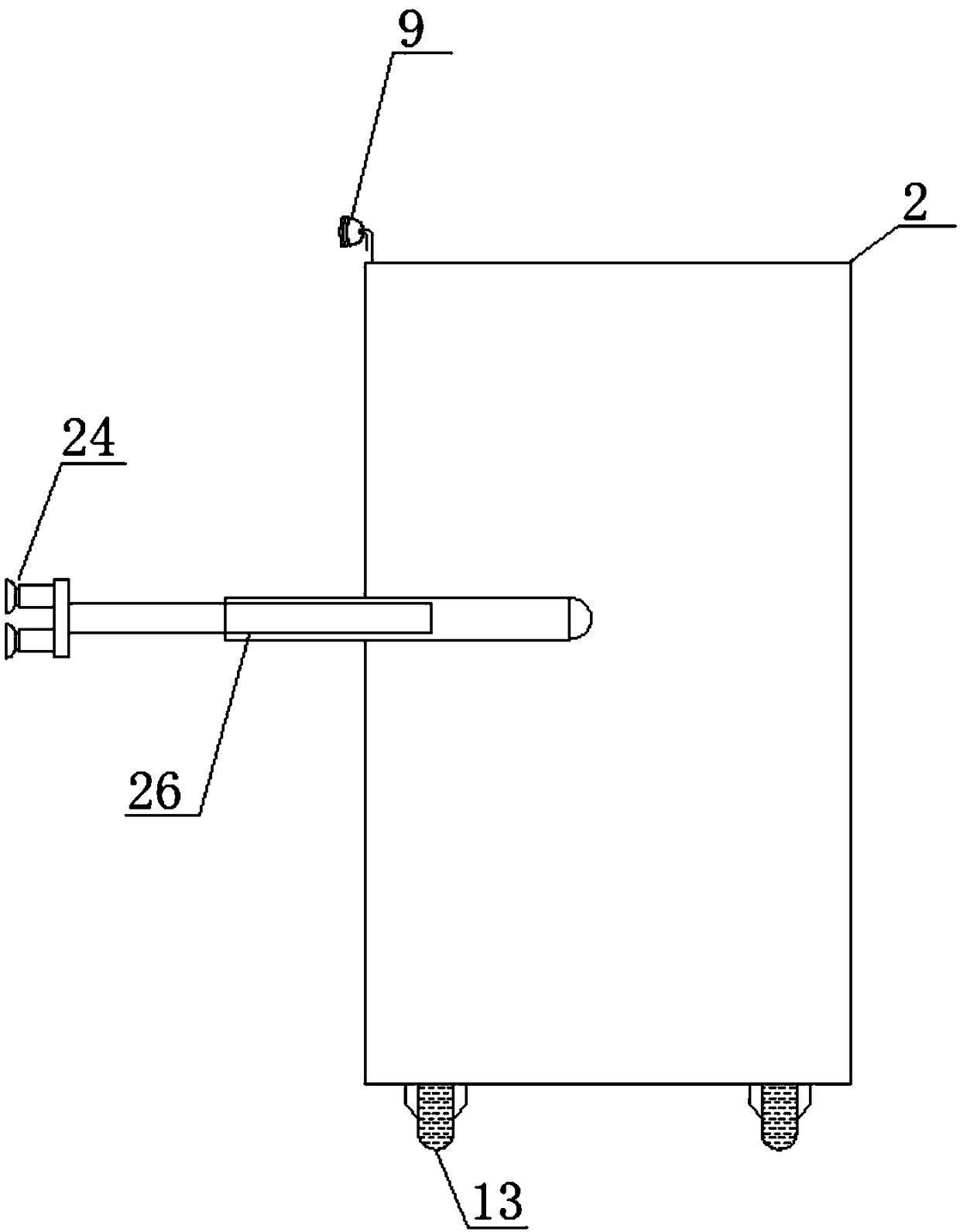
[0091] Such as Picture 11 As shown, also includes:

[0092] The laser rangefinder 25 detects the horizontal distance value between the split mechanism 2 and the electric vehicle and sends the horizontal distance value to the processor 4;

[0093] The processor 4 determines whether the horizontal distance value is greater than the adsorption range of the adsorption device 24;

[0094] If yes, the processor 4 calculates the difference between the horizontal distance value and the adsorption range;

[0095] The processor 4 outputs the second extension signal to the driving device 5, and the driving device 5 drives the electro-hydraulic push rod 26 to extend the length of the difference;

[0096] The processor 4 outputs a suction signal to the driving device 5, and the driving device 5 drives the suction device 24 to be adsorbed on the surface of the electric vehicle.

[0097] Specifically, during the charging process, the relative position of the split mechanism 2 and the electric vehicle...


PUM


Abstract

The invention discloses a split type charging equipment of an electric vehicle and a working method thereof. The equipment comprises a charging station, a split mechanism and a control mechanism, thecontrol mechanism comprises a processing unit, a driving device, a positioning device and a navigation device, the positioning device is used for obtaining the location information of the split mechanism, the navigation device is used for generating the moving route of the split mechanism, the charging station comprises a first connecting device, the first connecting device is connected with an input end of a battery, the split mechanism comprises a camera device, a cover opening device, a storage cavity, a charging device and a moving device, the camera device is used for obtaining the peripheral environment of the split mechanism, the charging device comprises the battery, a charging guiding wire, a charging plug, a second connecting device and a telescopic supporting frame, the chargingplug is connected with the charging guiding wire through the second connecting device, the telescopic supporting frame covers the charging guiding wire and the exterior of the charging plug, the cover opening device is connected with the driving device and used for opening a battery cavity of the electric vehicle, and the moving device is used for driving the split mechanism to move.

Description

Technical field [0001] The invention relates to the field of electric vehicles, in particular to a split type charging device for electric vehicles and a working method thereof. Background technique [0002] With the consumption of petroleum resources, the development of electric vehicles has become an inevitable trend. At present, there have been more hybrid or all-electric vehicles on the market, and electric vehicles have also been favored by people. Following this, the development of electric vehicle charging stations has also become inevitable, but under the current circumstances, the development of charging stations cannot match the development of electric vehicles, making electric vehicles unable to enter the homes of ordinary people in the short term. [0003] The establishment of a large-scale charging station requires the establishment of a dedicated charging network, which requires the transformation of the power grid, the investment cost is too high, and the application...

Claims


Application Information

Patent Timeline
IPC IPC(8): B60L53/30B60L53/34B60L53/35B60L53/36
CPCY02T10/70Y02T10/7072Y02T90/12
Inventor 侍雨
Owner 侍雨
Why Eureka
Try Eureka