
Metallographic sample preparation electrolytic corrosion device and method

An electrolytic corrosion and metallographic sample preparation technology, which is applied in the preparation of test samples, etc., can solve the problems of inaccurate determination of the corrosion end point, cumbersome test process, and the corrosion effect is greatly affected by human factors, and achieves a clear structure and morphology. , The effect of simple equipment structure and easy operation

Pending Publication Date: 2019-02-26
PLA NO 5719 FACTORY
View PDF10 Cites 0 Cited by
  • Summary
  • Abstract
  • Description
  • Claims
  • Application Information

AI Technical Summary

Problems solved by technology

However, the disadvantage is that due to different types of materials and batch differences, the corrosion effect of the electrolytic corrosion method is greatly affected by human factors, and in order to prevent the sample from being over-corroded, the electrolytic corrosion parameters are usually from slight corrosion parameters to higher corrosion parameters. The parameters are gradually excessive, the test process is cumbersome and the corrosion end point cannot be accurately determined
The above-mentioned patents all optimize the electrolytic corrosion process of metallographic samples and improve the corrosion effect to a certain extent, but they fail to solve the problem of accurately judging the end point of corrosion

Method used


Image

  • Metallographic sample preparation electrolytic corrosion device and method
  • Metallographic sample preparation electrolytic corrosion device and method

Examples


Embodiment Construction

[0020] The present invention will be further described below in conjunction with the accompanying drawings, but the protection scope of the present invention is not limited to the following description.

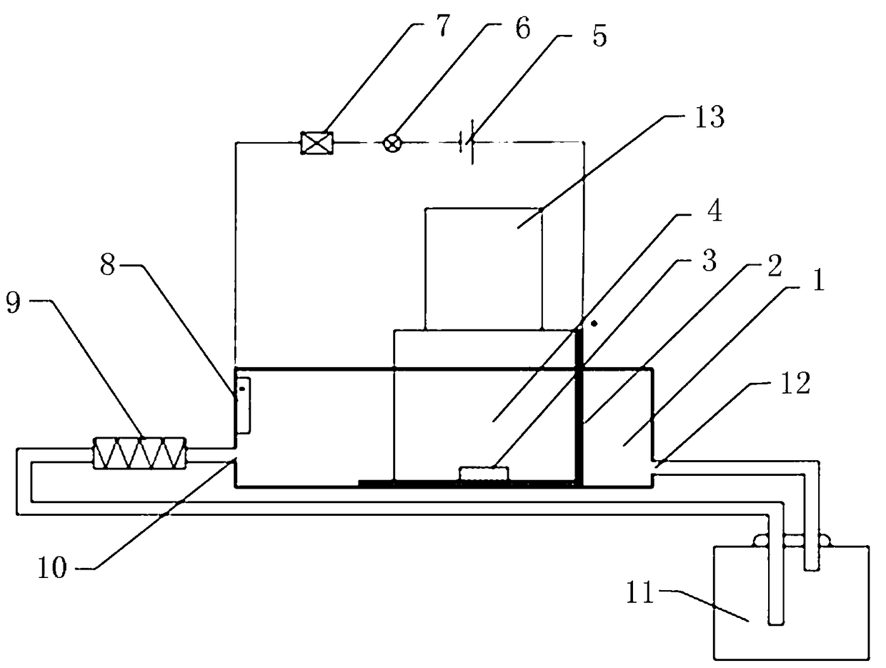
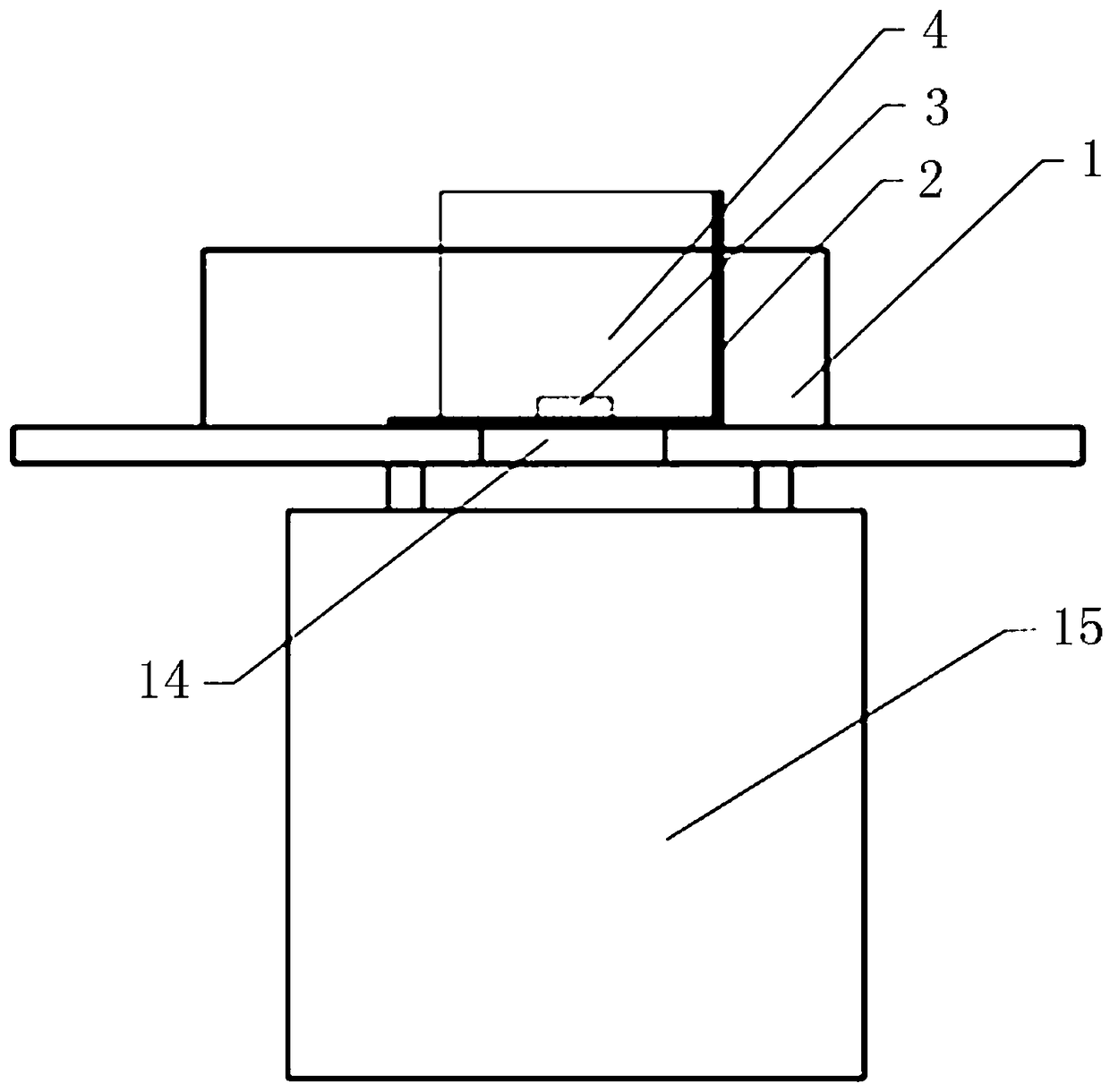
[0021] Such as Figure 1~2 As shown, a metallographic sample preparation electrolytic corrosion device and method, including an electrolytic cell 1, a metal mesh 2, a booster pump 9 and a power supply 5, the side wall of the electrolytic cell 1 is provided with a cathode plate 8, The cathode plate 8 is connected to the negative pole of the power supply 5, the metal mesh 2 is placed in the electrolytic cell 1, the bottom of the metal mesh 2 is circular and slightly larger than the diameter of the sample 3, the positive electrode of the power supply 5 is connected to the metal mesh 2, and the cathode plate 8 is provided with a Electrolyte solution inlet 10, electrolyte solution inlet 10 connects booster pump 9, booster pump 9 connects electrolyte bottle 11 through pipeline, ele...


PUM

PropertyMeasurementUnit
transmittivityaaaaaaaaaa

Abstract

The invention discloses a metallographic sample preparation electrolytic corrosion device and method. The metallographic sample preparation electrolytic corrosion device comprises an electrolytic bath(1), a metal net (2), a booster pump (9) and a power supply (5), wherein a negative plate (8) is arranged on the side wall of one side of the electrolytic bath (1) and is connected with a negative electrode of the power supply (5); the metal net (2) is arranged in the electrolytic bath (1); a positive electrode of the power supply (5) is connected with the metal net (2); an electrolyte inlet (10)is formed below the negative plate (8) and is connected with the booster pump (9); the booster pump (9) is connected with an electrolyte bottle (11) through a pipeline; the electrolytic bath (1) is also provided with an electrolyte outlet (12); the electrolyte outlet (12) is connected with the electrolyte bottle (11). The metallographic sample preparation electrolytic corrosion device and the metallographic sample preparation electrolytic corrosion method disclosed by the invention have the advantages that voltage parameters of electrolytic corrosion are adjusted in real time under the condition that the to-be-checked surface of a sample is focally observed by using a metallurgical microscope, so as to realize accurate determination of a corrosion end point.

Description

technical field [0001] The invention relates to the technical field of input tax detection devices, in particular to an electrolytic corrosion device and method for metallographic sample preparation. Background technique [0002] . Metallographic sample preparation usually includes four steps: cutting sample, mosaic sample, sample preparation and tissue evaluation. Among them, the sample preparation is to grind, polish and corrode the tissue after the sample is mounted, so as to determine the structure. Corrosion of metallographic specimens is often divided into chemical corrosion and electrolytic corrosion. Among them, electrolytic corrosion is that an external power source makes the oxidizing ions with high electrode potential discharge and reduce at the cathode, while the more active metal with low electrode potential in the anode area loses electrons and is oxidized, becoming cations and detaching from the surface of the material, forming anode corrosion. Due to the d...

Claims


Application Information

Patent Timeline
Patent Type & Authority Applications(China)
IPC IPC(8): G01N1/32
CPCG01N1/32
Inventor 胡萌张晓峰黄贵祥李晓超
Owner PLA NO 5719 FACTORY
Learn More