
Differential probe and non-contact voltage measuring device

A voltage measurement, non-contact technology, applied in the direction of measuring devices, only measuring voltage, measuring electrical variables, etc., can solve the problems of inability to obtain voltage values, high cost of differential probes, and large equipment volume, which is conducive to mass production. Application, good practicability, effect of small device size

Pending Publication Date: 2019-02-26
SOUTH CHINA UNIV OF TECH
View PDF0 Cites 9 Cited by
  • Summary
  • Abstract
  • Description
  • Claims
  • Application Information

AI Technical Summary

Problems solved by technology

[0002] Traditional differential probes are usually composed of two separate electrodes and transmit signals through wires. In non-contact voltage measurement application scenarios, the two electrodes need to be fixed with both hands, which is very inconvenient when working off the ground; or use a clip-on probe The electrodes are fixed, but the clip-on electrodes are bulky and inconvenient to carry; on the other hand, the cost of discrete differential probes is relatively high
[0003] The traditional contact meter first needs to destroy the insulation layer of the wire during installation, and the voltage value cannot be obtained at some measurement points where the insulation layer cannot be damaged. Therefore, a low-cost, easy-to-install, high-precision, and strong adaptability to the environment is urgently needed. Large-Scale Voltage Monitoring of Distribution Networks with Non-Contact Voltage Measuring Devices
[0004] Under the premise of not destroying the insulation layer of the wire, the thickness of the insulation layer of the line to be tested varies with the actual situation. Some traditional non-contact measurement methods with fixed parameters can only provide an estimated value with a large error and cannot be accurate. Measure the voltage value of the line under test
[0005] On the other hand, there are also some non-contact voltage measuring devices that measure the two wires of the zero line and the live line. The equipment is large in size and difficult to operate.

Method used


Image

  • Differential probe and non-contact voltage measuring device
  • Differential probe and non-contact voltage measuring device
  • Differential probe and non-contact voltage measuring device

Examples


Embodiment 1

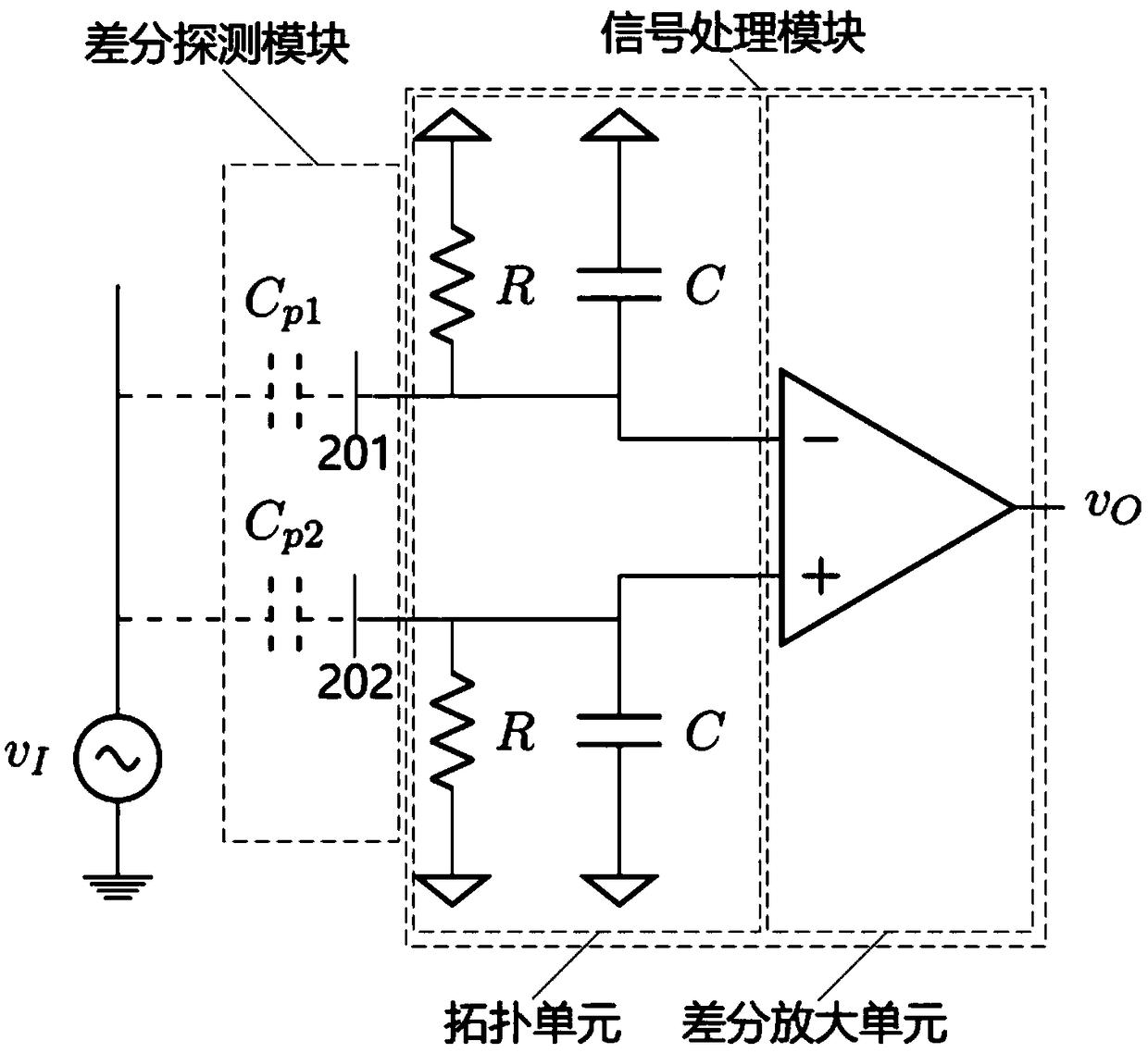
[0043] figure 1 A structural diagram of a non-contact voltage measurement system according to an embodiment of the present invention is shown. The non-contact voltage measurement system in the embodiment of the present invention includes a differential detection module, a signal processing module and a data processing module, and the differential detection module, the signal processing module and the data processing module are connected in sequence.

[0044] Among them, the differential detection module of the embodiment of the present invention is used to form two unequal first parasitic capacitances C with the line to be tested P1 and a second parasitic capacitance C P2 , and based on the first parasitic capacitance C P1 and a second parasitic capacitance C P2 Obtain the input voltage V of the line under test i (s).

[0045] Generally, a capacitance can always be formed between any two insulating metal objects, especially when the insulation distance is small, the capac...

Embodiment 2

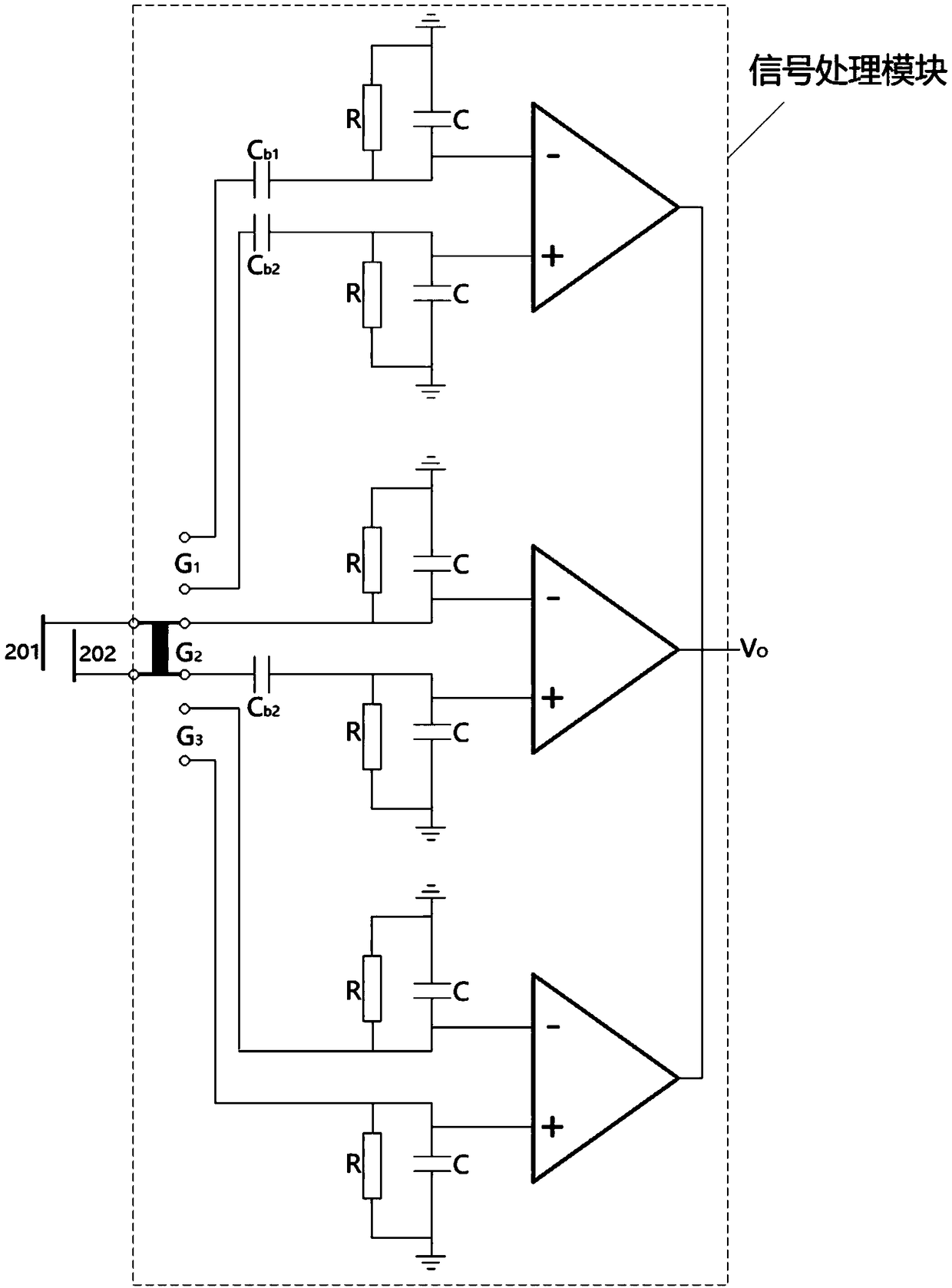
[0066] image 3 A structural diagram of a signal processing module according to an embodiment of the present invention is shown. Generally, a signal processing module includes a plurality of topology units and a topology switching unit.

[0067] The topology switching unit is respectively connected to the differential detection module and the plurality of topology units, and is used to switch the connection state between the plurality of topology units and the differential detection module;

[0068] The plurality of topological units have different transfer functions respectively, and are used to process the input voltage V of the line to be tested. i (s), generating the corresponding output value.

[0069] An embodiment of the present invention provides an implementation of a signal processing module. The signal processing module in the embodiment of the present invention includes a topology switching unit and three topology units. switch), the three topological units are G...

Embodiment 3

[0083] On the basis of the second embodiment, in order to simplify the module structure, it can be known from the signal processing mode of the signal processing module that only one differential amplification unit is working at the same time. Therefore, G 1 , G 2 , G 3 A differential amplifier unit can be shared to save cost.


PUM


Abstract

The invention provides a differential probe and a non-contact voltage measuring device. The differential probe is composed of two adjacent metal substrates in a circuit board, and the two metal substrates are separated by an insulating layer. Fixed capacitance Ca is formed between the two layers of metal substrates. The differential probe integrates two electrodes of the differential probe into the circuit board, and volume of the differential probe is reduced, and manufacturing cost of the differential probe is reduced. The non-contact voltage measuring device acquires an AC voltage signal ofa to-be-measured circuit through a capacity coupling non-contact method, and has good adaptability. An operation target is a single wire, the device is small in volume, and the device is easy to carry. Through two relay switches, the circuit has three kinds of topological structures. The number of components is few, and manufacturing cost is low, and the device is beneficial for mass production and application. Through a wireless transmission circuit, circuit voltage is uploaded to a cloud server, and circuit voltage data can be collected in a large-scale manner. The device has good practicability.

Description

technical field [0001] The invention relates to the field of voltage measurement, in particular to a differential probe and a non-contact voltage measurement device. Background technique [0002] Traditional differential probes are usually composed of two separate electrodes and transmit signals through wires. In non-contact voltage measurement application scenarios, the two electrodes need to be fixed with both hands, which is very inconvenient when working off the ground; or use a clip-on probe The electrodes are fixed, but the clip-on electrodes are bulky and inconvenient to carry; on the other hand, the cost of discrete differential probes is relatively high. [0003] The traditional contact meter first needs to destroy the insulation layer of the wire during installation, and the voltage value cannot be obtained at some measuring points where the insulation layer cannot be damaged. Therefore, a low-cost, easy-to-install, high-precision, and strong adaptability to the en...

Claims


Application Information

Patent Timeline
Patent Type & Authority Applications(China)
IPC IPC(8): G01R19/00
CPCG01R19/0084
Inventor 刘希喆江陶然
Owner SOUTH CHINA UNIV OF TECH
Learn More