
Fiber laser beam combiner and manufacturing method thereof

A technology of laser beam combiner and optical fiber beam, which is applied in the coupling of optical waveguides, instruments, optics, etc., can solve the problems of high process requirements and low yield rate of laser beam combiners, and achieves high beam quality, compact structure, and low cost. cost effect

Active Publication Date: 2020-10-02
常州莱特康光电科技有限公司
View PDF5 Cites 0 Cited by
  • Summary
  • Abstract
  • Description
  • Claims
  • Application Information

AI Technical Summary

Problems solved by technology

[0004] The purpose of the present invention is to provide a fiber laser beam combiner to solve the technical problems of low yield and high process requirements of the laser beam combiner in the prior art

Method used

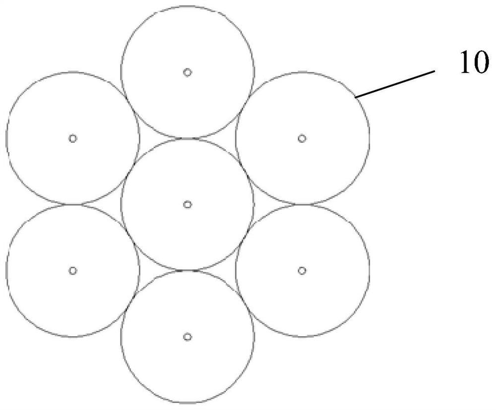
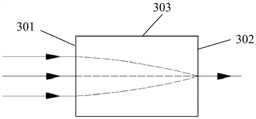
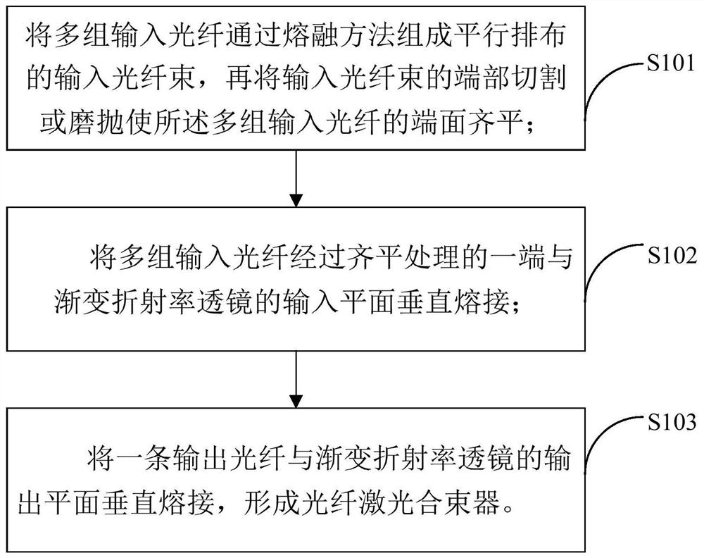

Image

  • Fiber laser beam combiner and manufacturing method thereof
  • Fiber laser beam combiner and manufacturing method thereof
  • Fiber laser beam combiner and manufacturing method thereof

Examples


Embodiment Construction

[0027] In order to make the object, technical solution and advantages of the present invention clearer, the present invention will be further described in detail below in conjunction with the accompanying drawings and embodiments. It should be understood that the specific embodiments described here are only used to explain the present invention, not to limit the present invention.

[0028] It should be noted that when a component is referred to as being “fixed on” or “disposed on” another component, it may be directly on the other component or indirectly on the other component. When an element is referred to as being "connected to" another element, it can be directly or indirectly connected to the other element. The orientation or positional relationship indicated by the terms "upper", "lower", "left", "right", etc. are based on the orientation or positional relationship shown in the drawings, and are for convenience of description only, rather than indicating or implying the ...


PUM


Abstract

The present invention relates to the technical field of optical devices, and provides a fiber laser beam combiner and a manufacturing method thereof. The fiber laser beam combiner comprises a plurality of input optical fibers and an output optical fiber which are connected through a gradually changed refractive index lens which is in a cylinder shape and comprises an input plane, an output plane and a side connected therebetween, the input optical fibers are in parallel and are in tapering vertical fusion with the input plane, and the output optical fiber is in parallel with the input opticalfiber and is in the vertical fusion of the output plane. The input optical fibers are connected with the output optical fiber through the gradually changed refractive index lens, and the light in theinput optical fiber are focused into the output optical fiber after passing through the input optical fibers. The optical fibers do not need corrosion tapering to avoid the problem that the optical fiber cladding surface is not smooth to generate loss, the structure is compact, the size is small, the light beam quality is high, the complex process steps are reduced, the processing difficulty and the process requirements are reduced, and the product yield can be obviously improved.

Description

technical field [0001] The invention belongs to the technical field of optical devices, and more specifically relates to a fiber laser beam combiner and a manufacturing method thereof. Background technique [0002] Fiber lasers have the advantages of good beam quality, small size, light weight, long life, and stable operation. They are widely used in industries such as long-distance communication, machining, laser marking, and medical treatment. As the application fields of fiber lasers become more and more extensive, the requirements for the output power of fiber lasers have reached the level of kilowatts or even 10,000 watts. [0003] At present, the output efficiency of a single fiber is at the kilowatt level, but due to the limitations of physical mechanisms such as thermal damage and safety considerations, in order to obtain higher laser output, the commonly used processing method is to use a laser beam combiner and a single fiber Combine multiple power units into one ...

Claims


Application Information

Patent Timeline
Patent Type & Authority Patents(China)
IPC IPC(8): G02B6/32G02B27/09
CPCG02B6/32G02B27/0994
Inventor 叶铭森董杰周扬
Owner 常州莱特康光电科技有限公司
Learn More