Fire early warning system and method for photovoltaic power station

A photovoltaic power station and fire early warning technology, applied in the direction of electric fire alarms, etc., can solve problems such as false alarms, heavy maintenance workload, and poor flexibility, and achieve simple and reliable systems, strong anti-interference capabilities, and long monitoring distances Effect

Inactive Publication Date: 2019-02-26
ZHUZHOU CSR TIMES ELECTRIC CO LTD
View PDF7 Cites 7 Cited by
  • Summary
  • Abstract
  • Description
  • Claims
  • Application Information

AI Technical Summary

Problems solved by technology

[0004] 1) The accuracy is low, only a certain local line segment can be used as the alarm unit, and the alarm point cannot be accurately located;
[0005] 2) The monitoring range is small, and the upper limit length of the general alarm unit is 200m;
[0006] 3) Susceptible to electromagnetic interference, often false alarms in strong electric environments
It can resist the interference of weak electric environment, but it cannot be free from any interference in the environment of strong electromagnetic field;
[0007] 4) The alarm temperature cannot be modified arbitrarily, only the set temperature can be alarmed, and the temperature status and temperature development trend can not be judged without alarming, and the flexibility is poor. For the more expensive analog 4-core cable temperature senso

Method used


Image

  • Fire early warning system and method for photovoltaic power station
  • Fire early warning system and method for photovoltaic power station
  • Fire early warning system and method for photovoltaic power station

Examples


Embodiment Construction

[0029] The implementation of the present invention will be described in detail below in conjunction with the accompanying drawings and examples, so as to fully understand and implement the process of how to apply technical means to solve technical problems and achieve technical effects in the present invention. It should be noted that, as long as there is no conflict, each embodiment and each feature in each embodiment of the present invention can be combined with each other, and the formed technical solutions are all within the protection scope of the present invention.

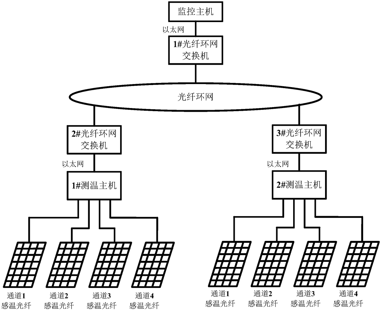
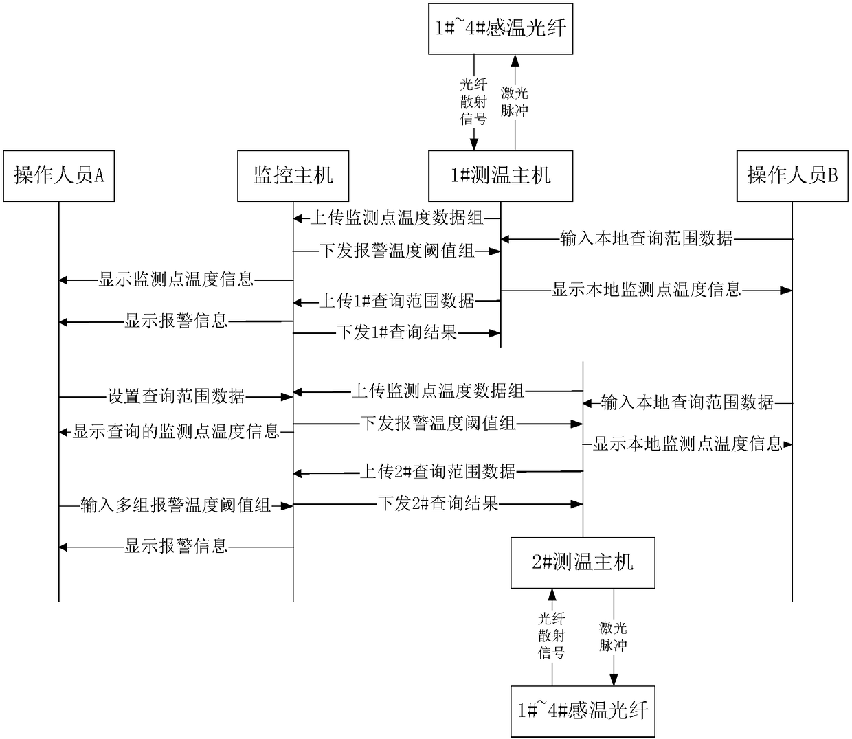
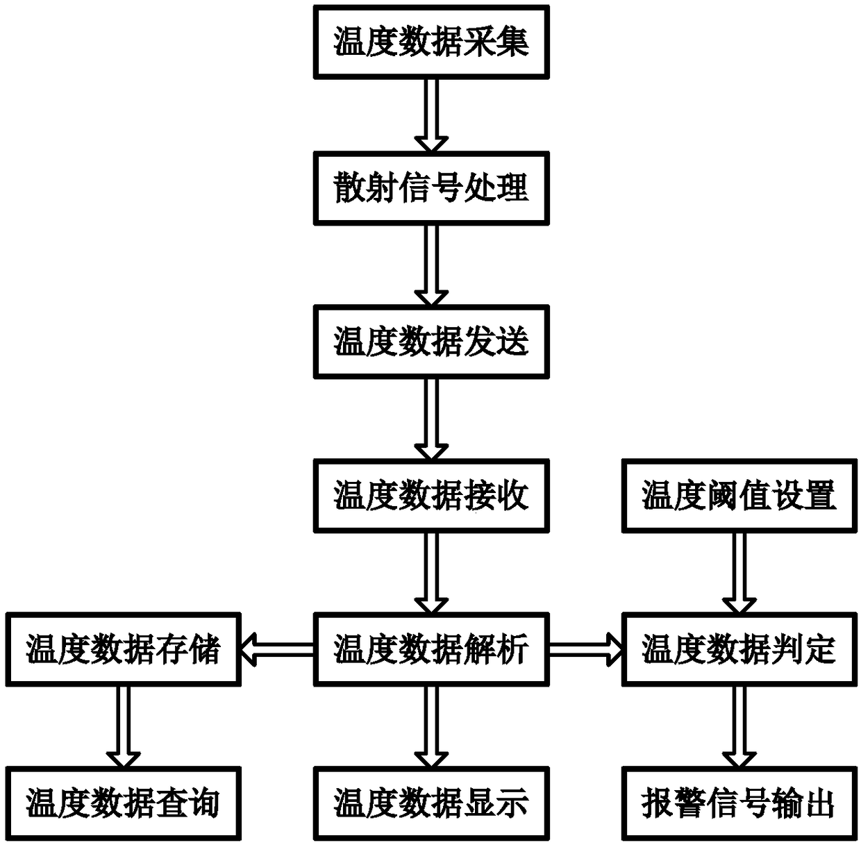
[0030] In order to overcome the deficiencies in the above-mentioned prior art, this embodiment proposes a fire warning system for photovoltaic power plants based on temperature-sensing optical fibers. Using the properties of temperature-sensing optical fibers and optical fiber equipment, the network topology and the entire network of the fire early warning system are constructed. Through the new implementatio...


PUM


Abstract

The invention discloses a fire early warning system for a photovoltaic power station. The fire early warning system for a photovoltaic power station includes a plurality of temperature-sensing opticalfibers arranged in the photovoltaic power station, a plurality of temperature measuring hosts and a monitoring host, wherein the plurality of temperature-sensing optical fibers use the self-containedmeter standard device to calibrate all the monitoring points in the corresponding optical fiber, and output the optical fiber scattering signals; each temperature measuring host is connected to several temperature-sensing optical fibers to collect the fiber scattering signals output by the temperature-sensing optical fibers connected to the each temperature measuring host in the preset interval,calculate the position data, the field temperature and the temperature level of each monitoring point, and output the monitoring point temperature data set under all the monitoring points; and the monitoring host is connected with the plurality of temperature measuring hosts to monitor all the temperature measuring hosts, receive and analyze the monitoring point temperature data set, perform dataanalysis and processing on the analysis results, and output alarm information. The fire early warning system for a photovoltaic power station has the advantages of a complete fire early warning mechanism, accurate positioning of monitoring point, long monitoring distance, high flexibility, and high anti-interference ability, and all the settings are completed in the terminal, and the whole systemis simple and reliable.

Description

technical field [0001] The invention relates to the technical field of photovoltaic power station alarm monitoring, in particular to a fire early warning system for a photovoltaic power station. Background technique [0002] With the deepening of the energy crisis, the photovoltaic industry has entered a period of rapid development in recent years. Rapid development will inevitably bring more and more safety hazards. Among them, the fire problem of photovoltaic power stations, especially the fire of distributed rooftop photovoltaic power stations, once Appearance may cause immeasurable personal and property losses. In order to reduce the occurrence of fire accidents, on the one hand, product quality should be improved, and on the other hand, preventive measures should be added. [0003] At present, the fire warning of photovoltaic power stations mostly adopts the temperature monitoring technology of the cable method. The cable is composed of two or more wires. When the ambie...

Claims


Application Information

Patent Timeline
IPC IPC(8): G08B17/06
CPCG08B17/06
Inventor 蹇芳唐海燕刘永丰廖资阳程宇旭郭积晶崔坚
Owner ZHUZHOU CSR TIMES ELECTRIC CO LTD
Why Eureka
Try Eureka