Slewing bearing overturning mechanism

A technology of turning mechanism and slewing bearing, applied in the field of machinery, can solve the problems of worker operation, low work efficiency, hidden dangers, etc., and achieve the effect of compact structure, convenient assembly, and guarantee of safety.

Inactive Publication Date: 2019-03-01
NANJING GONGDA CNC TECH
View PDF9 Cites 16 Cited by
  • Summary
  • Abstract
  • Description
  • Claims
  • Application Information

AI Technical Summary

Problems solved by technology

[0003] During the processing of the slewing bearing, the inner and outer rings and the assembly need to be turned 180° frequently. Due to its large size, the method of turning over by driving is mostly used at this stage, which has low work efficiency and has potential safety hazards for workers. In view of this, we propose a slewing bearing turning mechanism

Method used


Image

  • Slewing bearing overturning mechanism
  • Slewing bearing overturning mechanism
  • Slewing bearing overturning mechanism

Examples


Embodiment 1

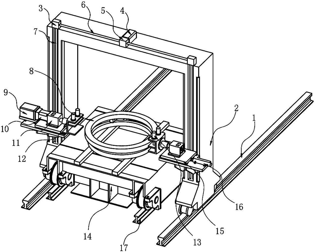
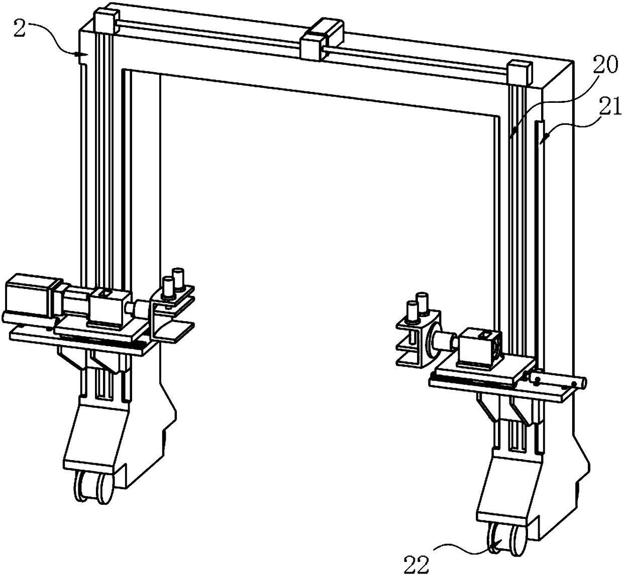
[0028] A slewing bearing turning mechanism, such as Figure 1-5 As shown, two ground rails 1 parallel to each other are included, a mobile trolley 14 is arranged between the two ground rails 1 and above it, a gantry bracket 2 is arranged on the two ground rails 1, and the side walls of the gantry bracket 2 A pair of opposite guide rail sliders 15 are arranged on the top, and a coupling assembly 11 is installed on the guide rail slider 15. A rotating motor 9 and a third reducer 10 are arranged behind the coupling assembly 11, and a rotating device 12 is provided in front of the coupling assembly 11. , the output shaft of the rotating motor 9 is coaxially connected with the input shaft of the third reducer 10, the output shaft of the third reducer is fixedly connected with the rear end of the rotating device 12 through the coupling assembly 11, and the slewing bearing 8 is placed on the moving trolley 14 .

[0029] In this embodiment, the top of the gantry support 2 is provided...

Embodiment 2

[0035] In specific use, in order to facilitate the movement of the whole device and the convenient adjustment of the position of the slewing bearing 8, the inventor made an improvement on the basis of Embodiment 1. As a preference, first Roller 22, the first roller 22 is clamped on the ground rail 1 and can roll back and forth on the ground rail 1, the bottom end of the mobile trolley 14 is symmetrically equipped with a second roller 140, and the bottom end of the second roller 140 is provided with a rail 17 , the second roller 140 is clamped on the rail 17 and can roll back and forth on the rail 17, so that the whole gantry bracket 2 can be moved to adjust the position, and the mobile trolley 14 can be set to roll back and forth. 8 for processing, greatly improving work efficiency.

[0036] Specifically, both the ground rail 1 and the vehicle rail 17 are installed on the ground or the workbench by bolts to ensure their stability.

Embodiment 3

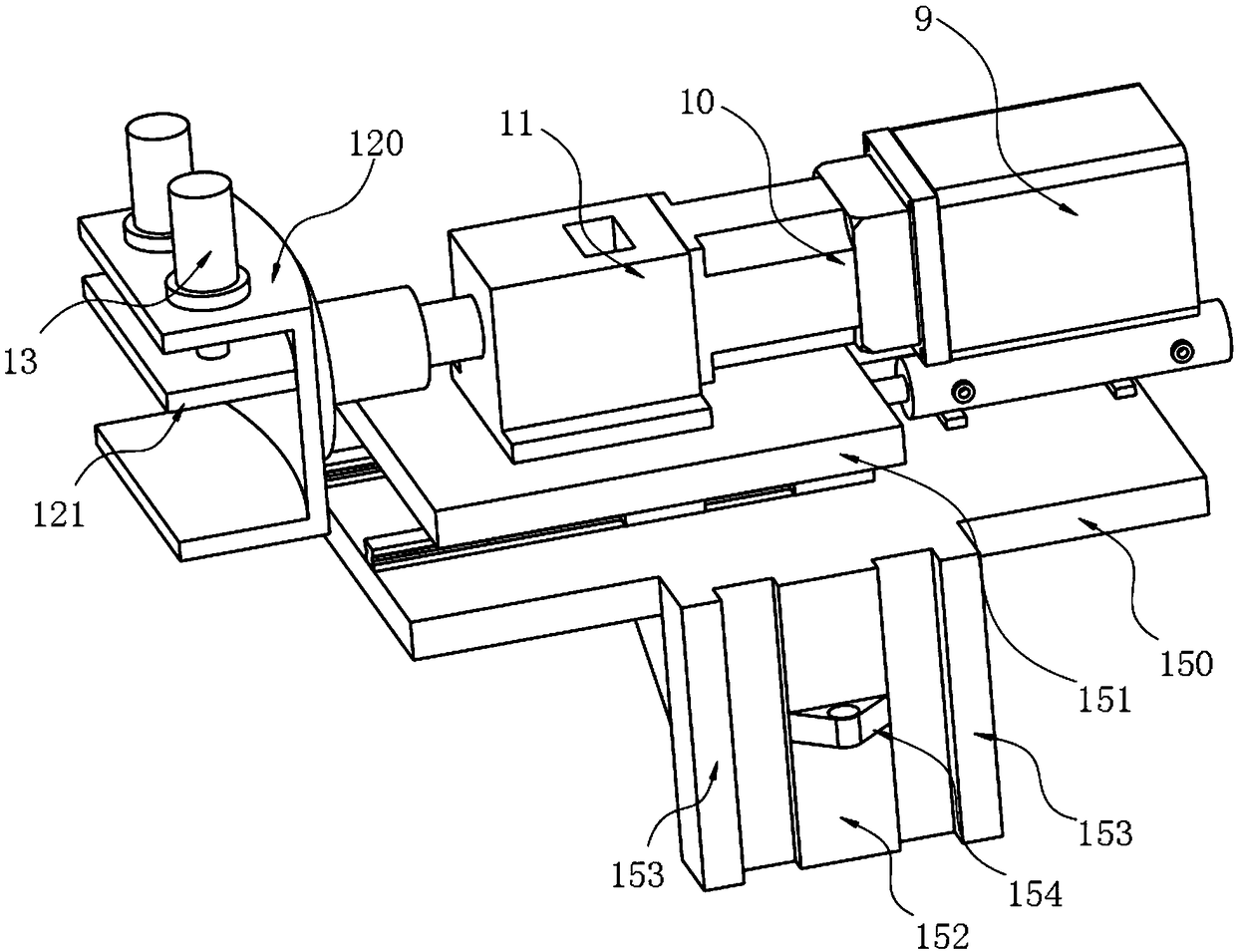
[0038] In order to improve the accuracy and stability of the rotating device 12 during rotation, the inventors made improvements on the basis of Embodiment 1, as a preference, as Figure 6 As shown, the coupling assembly 11 includes a bearing seat 110, and a coupling 111 is provided inside the bearing seat 110, and the coupling 111 is coaxially fixedly connected with the output shaft of the third reducer 10, and the main shaft of the jaw 120 passes through the bearing seat 110 is connected coaxially with the shaft coupling 111, and is locked and fixed by the lock nut 112. A pressure plate 113 is provided at the joint between the lock nut 112 and the inner wall of the bearing seat 110, and the main shaft of the jaw 120 and the inner wall of the bearing seat 110 They are rotationally connected by a plurality of bearings 114, preferably three in this embodiment, and the cooperation between the bearing housing 110 and the coupling 111 makes the third reducer 10 more stable and accu...


PUM


Abstract

The invention relates to the technical field of machinery, in particular to a slewing bearing overturning mechanism. The slewing bearing overturning mechanism comprises two ground rails and a travelling trolley, wherein the two ground rails are parallel to each other; the travelling trolley is arranged between the two ground rails and above the two ground rails; a gantry bracket is arranged on thetwo ground rails; a pair of opposite guiding rail sliders is arranged on the side wall of the gantry bracket; a connecting assembly is arranged on the guiding rail sliders; a rotating motor and a third speed reducer are arranged behind the connecting assembly; a rotating device is arranged in front of the connecting assembly; an output shaft of the rotating motor is coaxially connected with an input shaft of the third reducer; and an output shaft of the third reducer is fixedly connected to the rear end of the rotating device through the connecting assembly. By using the slewing bearing overturning mechanism, the inner ring, the outer ring and assemblies of a slewing bearing are automatically overturned to facilitate the machining and assembling of the slewing bearing. The slewing bearingoverturning mechanism has the advantages that the structure is compact, the assembling is convenient, the occupation of a crane is avoided, the safety of workers is ensured, and the overturning efficiency is improved.

Description

technical field [0001] The invention relates to the technical field of machinery, in particular to a slewing support turning mechanism. Background technique [0002] The slewing ring is a key mechanical component developed rapidly in recent decades, which can realize the functions of relative rotation of two structures and load transmission. Compared with ordinary rolling bearings, it can withstand axial load, radial load and overturning moment, and has small structural size, large intermediate space, small turning resistance, flexible rotation, simple and compact structure, and convenient installation and maintenance. Therefore, slewing bearings are widely used, from the earliest excavators and cranes, to other fields. Mainly used in lifting machinery (port cranes, truck cranes, tower cranes), construction machinery (excavators), chemical machinery, medical equipment, military equipment (radar, tanks, etc.), wind power equipment and entertainment facilities and other field...

Claims


Application Information

Patent Timeline
Patent Type & Authority Applications(China)
IPC IPC(8): B65G35/00B65G47/248B23P19/00B66C5/02B66C25/00
CPCB23P19/002B65G35/00B65G47/248B66C5/02B66C25/00
Inventor 喻先勇王华崔君君洪荣晶
Owner NANJING GONGDA CNC TECH
Why Eureka
Try Eureka