
Controllable nanometer graphene cutting method

A graphene and nanotechnology, applied in nanotechnology, nanotechnology, chemical instruments and methods, etc., can solve the problem of poor edge roughness and chirality control, inability to effectively control the shape of graphene, and lack of good chirality in carbon nanotubes. Control and other issues to achieve the effect of precise edge

Active Publication Date: 2019-03-01
XIAMEN UNIV
View PDF5 Cites 1 Cited by
  • Summary
  • Abstract
  • Description
  • Claims
  • Application Information

AI Technical Summary

Problems solved by technology

For example, electron beam lithography has poor control over the roughness and chirality of the edges of graphene trimming; carbon nanotube axial tearing lacks good control over the edge chirality; metal particle etching and electron beam-induced tearing cannot Efficient control over the shape of graphene

Method used


Image

  • Controllable nanometer graphene cutting method
  • Controllable nanometer graphene cutting method
  • Controllable nanometer graphene cutting method

Examples


Embodiment Construction

[0028] The present invention will be further described below by two embodiments and accompanying drawing, will utilize nano-knife to carry out detailed implementation method introduction to two smooth cuttings that graphene is carried out, in addition to cutting a piece of graphene of irregular shape into parallelogram The embodiment of the present invention is briefly introduced and illustrated with accompanying drawings.

[0029] 1. Depositing carbon on the tip of the tungsten tip to make a nanoknife

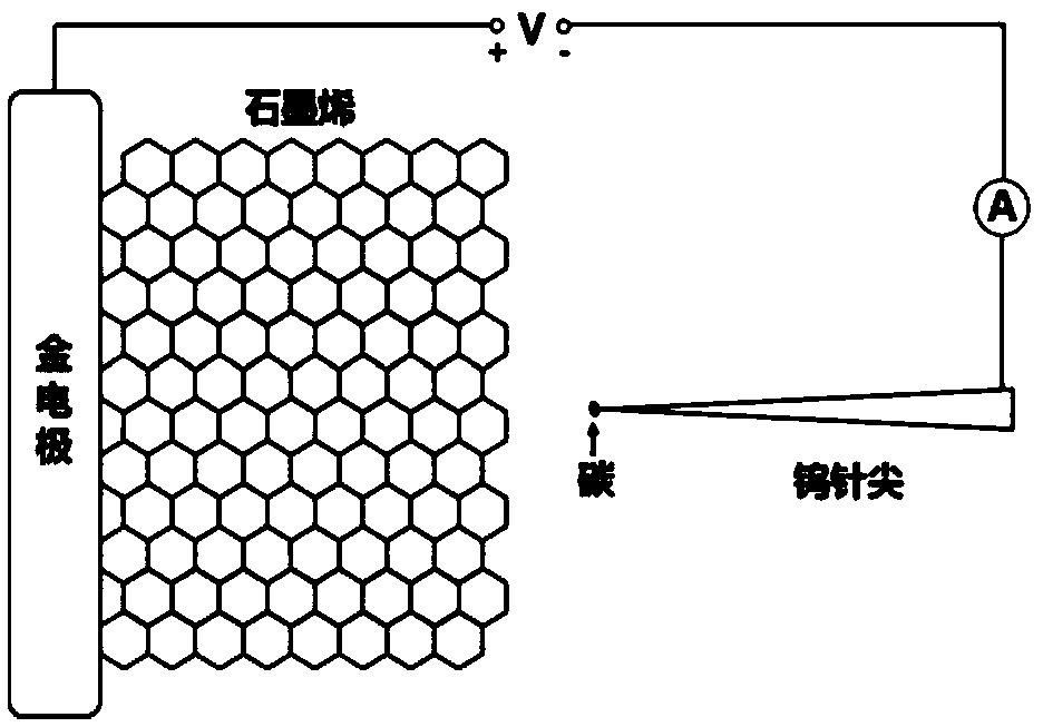
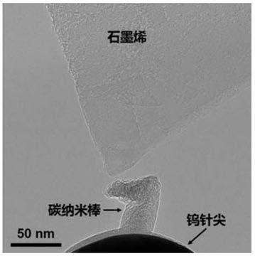
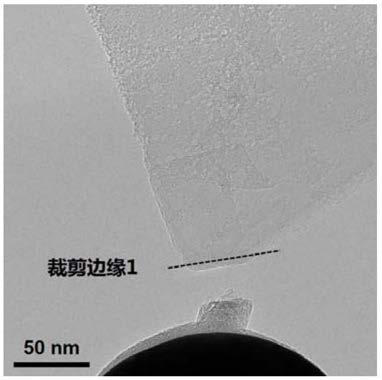
[0030] A controllable nano-cut graphene method provided by the present invention is implemented in a transmission electron microscope, figure 1 It is a schematic diagram of the cutting process. The gold electrode is fixed, and the graphene is adhered to the edge of the gold wire electrode. The nanoknife made of tungsten needle tip and carbon structure can move in three dimensions, and the minimum step size can reach the nanometer scale. On the electrodes at both ends A bias v...


PUM

PropertyMeasurementUnit
diameteraaaaaaaaaa
surface roughnessaaaaaaaaaa

Abstract

The invention discloses a controllable nanometer graphene cutting method, and relates to graphene. An amorphous carbon nanorod deposits at the tip end of a tungsten tip to be recrystallized through afocused electron beam, or nanometer carbon onions or graphite flakes are directly attached to the tip end of the tungsten tip, and a nanometer knife is prepared; constant bias voltages are exerted onthe tungsten tip and electrodes at the two ends of a golden wire, the nanometer knife is precisely moved according to the nanometer dimension step length, and the arbitrary precise cutting is conducted on the edge of graphene step by step. Through the cutting technology, any wanted shapes and sizes can be obtained, and the cut edges are smooth. By taking electron diffraction pictures of graphene,all chiral directions can be obtained and the edges of corresponding chiral structures are cut. Fewer layers of graphene of any shapes and patterns can be cut out instead of only obtaining angle-fixededge shapes like metal particle etching. Controllable cutting is conducted on the crystal structure and chirality of the cut edges, the cut edges are quite precise and smooth, and the roughness degree is 1-2 nm or lower.

Description

technical field [0001] The invention relates to graphene, in particular to a method for controllable nano-cut graphene. Background technique [0002] Nanoscience and technology is one of the most important research fields at present. The development of nanomaterials has played a huge role in promoting the progress of science and technology. Carbon nanomaterials are a new type of nanomaterials with great development potential. In 2004, two scientists from the University of Manchester, Andre Geim and Konstantin Novoselov, used micromechanical exfoliation to separate graphene (a carbon atom with SP 2 Monoatomic layer graphite formed by hybridization). Theoretical carrier mobility of graphene at room temperature > 250000cm 2 V -1 the s -1 , coupled with its excellent properties such as force, heat, and light, makes it have broad application prospects in the fields of materials, energy, and electronics, and has attracted great research interest. [0003] It is well known ...

Claims


Application Information

Patent Timeline
Patent Type & Authority Applications(China)
IPC IPC(8): C01B32/194B82Y30/00B82Y40/00
CPCB82Y30/00B82Y40/00C01B32/194
Inventor 王鸣生赵龙泽程勇李欣张桥保
Owner XIAMEN UNIV
Learn More