Pneumatic shunt well control system and shunt method

A technology of control system and diversion well, applied in sewage diversion, control system of pneumatic diversion well, municipal rainwater field, can solve the problem of high cost of electronic control hydraulic control

Pending Publication Date: 2019-03-01
WUHAN SHENGYU DRAINING SYST
View PDF0 Cites 0 Cited by
  • Summary
  • Abstract
  • Description
  • Claims
  • Application Information

AI Technical Summary

Problems solved by technology

[0005] Aiming at the defects of safety problems of electric control and high cost of hydraulic control in the prior art, a pneumatic diversion well control system and diversion method are provided

Method used


Image

  • Pneumatic shunt well control system and shunt method
  • Pneumatic shunt well control system and shunt method
  • Pneumatic shunt well control system and shunt method

Examples


Embodiment 1

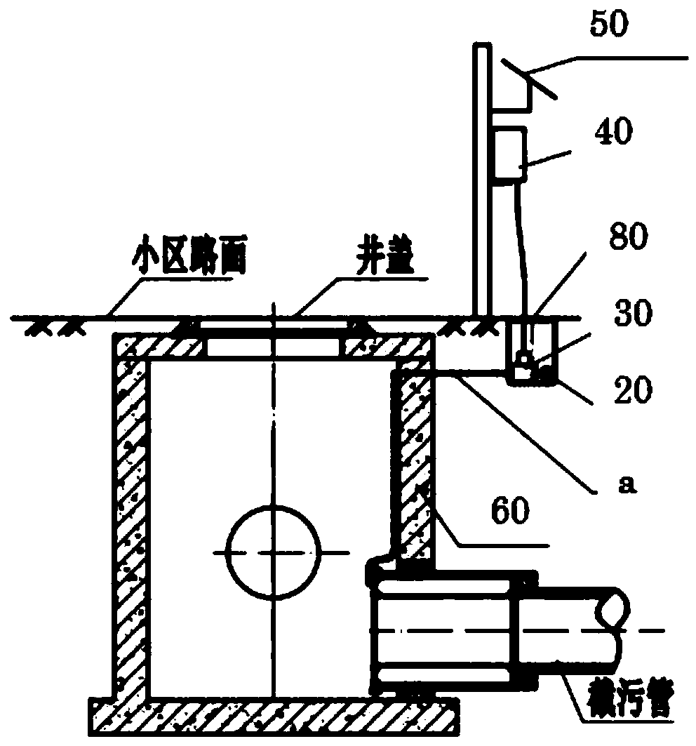
[0163] figure 1 It is a schematic structural diagram of the control system of the pneumatic diverter well with one inlet and two outlets, double airbags or pneumatic pinch valve in Embodiment 1.

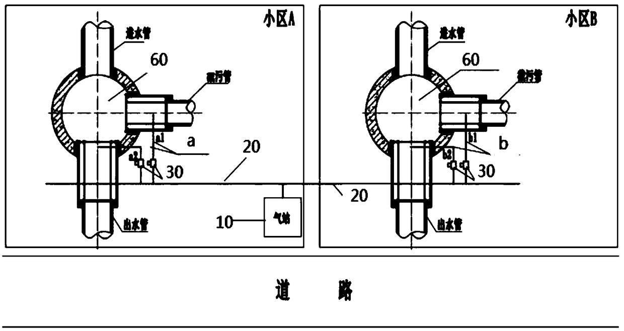
[0164] figure 2 for figure 1 top view.

[0165] see figure 1 As shown, the embodiment of the present invention (Form 1) provides a schematic structural diagram of a pneumatic diversion well control system with one inlet and two outlets, double airbags or pneumatic pipe pinch valves, which is used to control the sewage and rainwater in the drainage pipes of multiple areas in the area. For diversion, the drainage pipe can be a rainwater pipe of diversion system or a confluence pipe of confluence system, such as figure 1 As shown, a schematic structural diagram of a pneumatic diverter well control system with one inlet and two outlet double airbags or a pneumatic pipe pinch valve, which is used to divert the fluid in the drain pipe, including a compressed air source 10, a gas deliv...

Embodiment 2

[0224] In the first embodiment above, the air bag or pneumatic pinch valve installed on the first water outlet pipe and the second water outlet pipe are connected to the same main gas delivery pipe through the gas delivery branch pipe. In this embodiment, two main pipes can also be connected separately. : The first air bag or pneumatic pinch valve is connected to one gas delivery main pipe, and the second air bag or pneumatic pipe pinch valve is connected to another gas delivery main pipe.

Embodiment 3

[0226] Figure 7 It is a structural schematic diagram of the control system of the pneumatic diverter well with one inlet and two outlets, single air bag or pneumatic pinch valve in the third embodiment.

[0227] Such as Figure 7 As shown, form three, when the level of the first outlet is higher than the level of the second outlet, an airbag or pneumatic pinch valve is set, that is, the second airbag or pneumatic pinch valve, and the second airbag or pneumatic pinch valve is set On the end of the pipeline connected to the second outlet and close to the second outlet, the sewage and / or initial rainwater discharged into the diversion well is discharged into the sewage pipe through the second outlet. The middle and later stage rainwater that enters, because the second outlet is closed at this moment, the water level rises and surpasses the height of the second outlet and directly overflows through the first outlet and is led into the first water outlet pipe.

[0228] The contr...


PUM


Abstract

The invention discloses a pneumatic shunt well control system, which comprises a compression air source, a gas conveying main pipe, gas conveying branch pipes, control valves which are each arranged on the corresponding gas conveying branch pipes, and at least two unit area, wherein each unit area is provided with a pneumatic shunt well; the pneumatic shunt wells are composed of pneumatic well main bodies and pneumatic intercepting components; the first water outlets are connected to a natural water body or a rainwater pipe by virtue of first water discharge pipes, and the second water outletsare connected to a sewage pipe or a sewage disposal facility or a storage pond or an initial rainwater pipe or an initial rainwater disposal facility by virtue of second water discharge pipes; a pneumatic intercepting component is at least arranged on the second water discharge pipe; the pneumatic intercepting components in all unit areas are connected to the gas conveying main pipe by virtue ofthe corresponding gas conveying branch pipes; the control valves are arranged on the gas conveying branch pipes; and each control valve is used for controlling inflating / deflating statuses of the pneumatic intercepting components which are connected to the corresponding gas conveying branch pipes and for controlling intercepting and conducting states of the water outlets of the pneumatic intercepting components.

Description

technical field [0001] The invention relates to municipal rainwater and sewage diversion, in particular to a control system for a pneumatic diversion well, which belongs to the technical fields of civil buildings and municipal water supply and drainage. Background technique [0002] At present, in the diversion well, abandonment well and interception well system, the system is composed of water inlet pipe, outlet pipe and sewage pipe, and the domestic sewage in the drainage pipe or the initial rainwater and the later rainwater are diverted. Among them, the domestic sewage or The initial rainwater is intercepted to the sewage pipe and then transported to the sewage treatment plant for treatment and discharged after reaching the standard (further, the initial rainwater can be stored or intercepted to the sewage treatment plant for treatment and discharged after reaching the standard), and the middle and late rainwater is directly discharged into the natural water body. [0003...

Claims


Application Information

Patent Timeline
IPC IPC(8): E03F1/00E03F5/10
CPCE03F1/00E03F5/10E03F5/101E03F5/105E03F5/107E03F2201/00
Inventor 周超李习洪
Owner WUHAN SHENGYU DRAINING SYST
Why Eureka
Try Eureka