Tunnel supporting layer mold spraying mechanism and method

A technology for tunnels and fine-tuning mechanisms, applied in tunnels, tunnel linings, earthwork drilling and mining, etc., can solve the problems of lack of equipment, equipment, and very complicated control action requirements, so as to reduce difficulty, improve construction efficiency and construction quality, and increase coordination sexual effect

Pending Publication Date: 2019-03-01
SICHUAN LANHAI ENG EQUIP MFG CO LTD
View PDF15 Cites 6 Cited by
  • Summary
  • Abstract
  • Description
  • Claims
  • Application Information

AI Technical Summary

Problems solved by technology

[0008] However, during the mold spraying operation, the template mechanism used is very different from the traditional fixed template, and it needs to be constantly adjusted dynamically, and the position of the nozzle assembly relative to the template mechanism and relative to the mold cavity must be constantly adjusted. Adjustment, the requirements for the control action are very complicated and must be precise, which puts forward high requirements on the overall performance of the mold spraying mechanism, and there is no ready-made equipment for how to design the mold spraying mechanism for the tunnel support layer , equipment for reference, in the prior art, it is difficult to meet the above requirements

Method used


Image

  • Tunnel supporting layer mold spraying mechanism and method
  • Tunnel supporting layer mold spraying mechanism and method
  • Tunnel supporting layer mold spraying mechanism and method

Examples


Embodiment 1

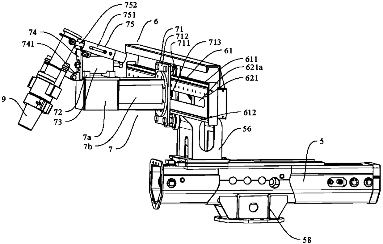
[0058] The mold spraying mechanism of the tunnel support layer includes a nozzle assembly 9, a template mechanism 8 and an injection system II. The nozzle assembly 9 is connected to the injection system II, and the nozzle assembly 9 is arranged above the template mechanism 8. The template mechanism 8 can The rock wall forms a mold cavity to be poured; the injection system II sends concrete to the nozzle assembly 9, and the nozzle assembly 9 injects concrete into the mold cavity in a direction not perpendicular to the rock wall above the formwork mechanism 8. The spray head assembly 9 is connected with a spray head fine-tuning mechanism, which can control the angle of the spray head 9 assembly relative to the template mechanism / cavity, so that the angle / direction of spraying the spray head assembly into the mold cavity can be adjusted.

[0059] The nozzle fine-tuning mechanism includes a pitch fine-tuning mechanism and a rotation fine-tuning mechanism, wherein the nozzle assembl...

Embodiment 2

[0063] This embodiment provides the specific structure of the nozzle fine-tuning mechanism on the basis of Embodiment 1. The nozzle fine-tuning mechanism includes a pitch fine-tuning mechanism and a rotation fine-tuning mechanism, wherein the nozzle assembly 9 is connected to the pitch fine-tuning mechanism and / or the rotation fine-tuning mechanism; The pitch fine-tuning mechanism can adjust the pitch angle / direction of the spray head assembly 9; the rotation fine-adjustment mechanism can adjust the rotation angle / direction of the spray head assembly 9; The angle / orientation relative to the cavity to ensure the effect and quality of injection casting.

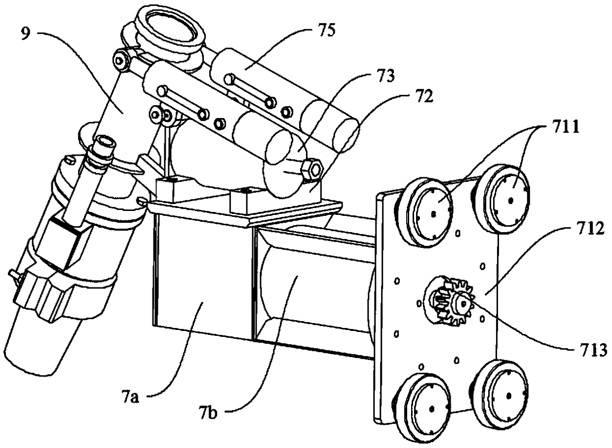
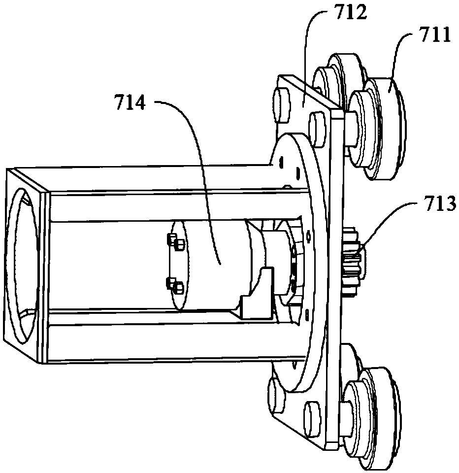
[0064] The fine-tuning mechanism also includes a nozzle fixing seat 7, and the rotary fine-tuning mechanism is fixed on the nozzle fixing seat 7; the pitch fine-tuning mechanism and the nozzle assembly 9 are all arranged on the rotary fine-tuning mechanism, and the pitch fine-tuning mechanism and the nozzle assembly 9 are integr...

Embodiment 3

[0068] In this embodiment, on the basis of Embodiment 2, the displacement control of the nozzle assembly 9 relative to the mold cavity (template assembly 8 ) is realized by connecting the nozzle fine-adjustment mechanism with the nozzle displacement mechanism. The nozzle fine-tuning mechanism, the nozzle displacement mechanism, the nozzle assembly 9, and the template mechanism 8 jointly form the nozzle moving assembly mechanism, so as to control the longitudinal and lateral distance relationship between the nozzle assembly 9 relative to the mold cavity, and the angle relative to the mold cavity / direction relationship.

[0069] The nozzle displacement mechanism includes a longitudinal movement mechanism and a lateral movement mechanism; the longitudinal movement mechanism and / or the lateral movement mechanism is provided with a nozzle fine-tuning mechanism, and the longitudinal movement mechanism can adjust the displacement of the nozzle fine-adjustment mechanism and the nozzle...


PUM


Abstract

The invention discloses a tunnel supporting layer mold spraying mechanism and method. The mold spraying mechanism comprises a spray head assembly, a mold plate mechanism and an injection system, wherein the injection system is connected with the spray head assembly; the spray head assembly is arranged on the upper part of the mold plate mechanism, and a mold cavity to be poured is formed by the mold plate mechanism and a rock wall; the injection system conveys concrete to the spray head assembly, and the spray head assembly sprays the concrete into the mold cavity from the upper part of the mold plate mechanism in the direction not perpendicular to the rock wall. According to the innovatively designed tunnel supporting layer mold spraying mechanism and method and based on the actual situation of the mold cavity between the mold plate mechanism and the excavated rock wall, the displacement, the angle, the direction, the height and the like of the spray head assembly can be adaptively adjusted, the controlling difficulty is lowered, and the controlling accuracy is improved; meanwhile, a mold spraying material agent injection system enables the concrete and an accelerator to be mixedquickly, adequately and evenly; and then the mixed concrete can be sprayed into the mold cavity and a supporting layer is formed rapidly, and the purpose of quickly reinforcing the tunnel rock wall isachieved.

Description

technical field [0001] The invention belongs to the technical field of construction machinery, and in particular relates to a mold spraying mechanism and a mold spraying method for a tunnel support layer. Background technique [0002] In the initial support construction of the tunnel, the construction method of directly spraying concrete on the excavation surface is adopted, and the spraying concrete method is divided into two types: mechanical arm spraying and manual spraying. The current direct shotcrete construction method has the following disadvantages: [0003] The rebound rate is high. Now there is 20%-40% rebound in the construction process, and the rebound material cannot be recycled, resulting in great waste, which is the main reason for the high construction cost. [0004] The amount of quick-setting agent is large, and the construction method of direct spraying concrete requires that the concrete needs to be bonded to the excavation surface within a short time a...

Claims


Application Information

Patent Timeline
Patent Type & Authority Applications(China)
IPC IPC(8): E21D11/10
CPCE21D11/102E21D11/105
Inventor 蓝传雯
Owner SICHUAN LANHAI ENG EQUIP MFG CO LTD
Why Eureka
Try Eureka