High-temperature corrosion and erosion testing device of bent pipe column of oil well pipe

A technology of high-temperature corrosion and test equipment, which is applied in the direction of measuring equipment, weather resistance/light resistance/corrosion resistance, instruments, etc., can solve the problems of not being able to simulate the erosion and corrosion of oil well pipe strings, and cannot provide erosion and corrosion thermodynamic information, etc., to meet the requirements of The effect of experimenting with demand

Active Publication Date: 2016-03-16
BC P INC CHINA NAT PETROLEUM CORP +1
View PDF9 Cites 13 Cited by
  • Summary
  • Abstract
  • Description
  • Claims
  • Application Information

AI Technical Summary

Problems solved by technology

[0006] The first type of test device can obtain the erosion amount, corrosion amount and the increase amount of the erosion-corrosion effect under the combined action of erosion and corrosion in the same set of devices; the second and third simulation devices can only change the fluid erosion Simulate the erosion of the oil well string by adjusting the velocity and adjusting the erosion angle
None of the above devices can simulate the erosion and corrosion of the oil well string under stress and buckling; and the above devices only use the weight loss of the sample to characterize the erosion corrosion rate, and cannot provide the thermodynamic information of erosion corrosion

Method used


Image

  • High-temperature corrosion and erosion testing device of bent pipe column of oil well pipe
  • High-temperature corrosion and erosion testing device of bent pipe column of oil well pipe
  • High-temperature corrosion and erosion testing device of bent pipe column of oil well pipe

Examples


Embodiment Construction

[0031] The present invention will be further described in detail below in conjunction with specific embodiments, which are explanations of the present invention rather than limitations.

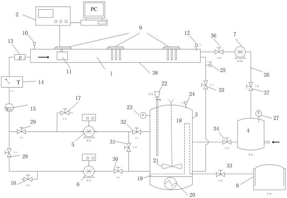
[0032] Such as figure 1 As shown, the present invention proposes a test device for evaluating the high-temperature corrosion and erosion performance of oil well tubular buckling strings, which includes an erosion corrosion channel 1, an electrochemical workstation 2, a storage tank 3, and an air supply tank 4 , a gas flow controller 5 , a liquid flow controller 6 , a vacuum pump 7 and a waste gas and liquid treatment system 8 .

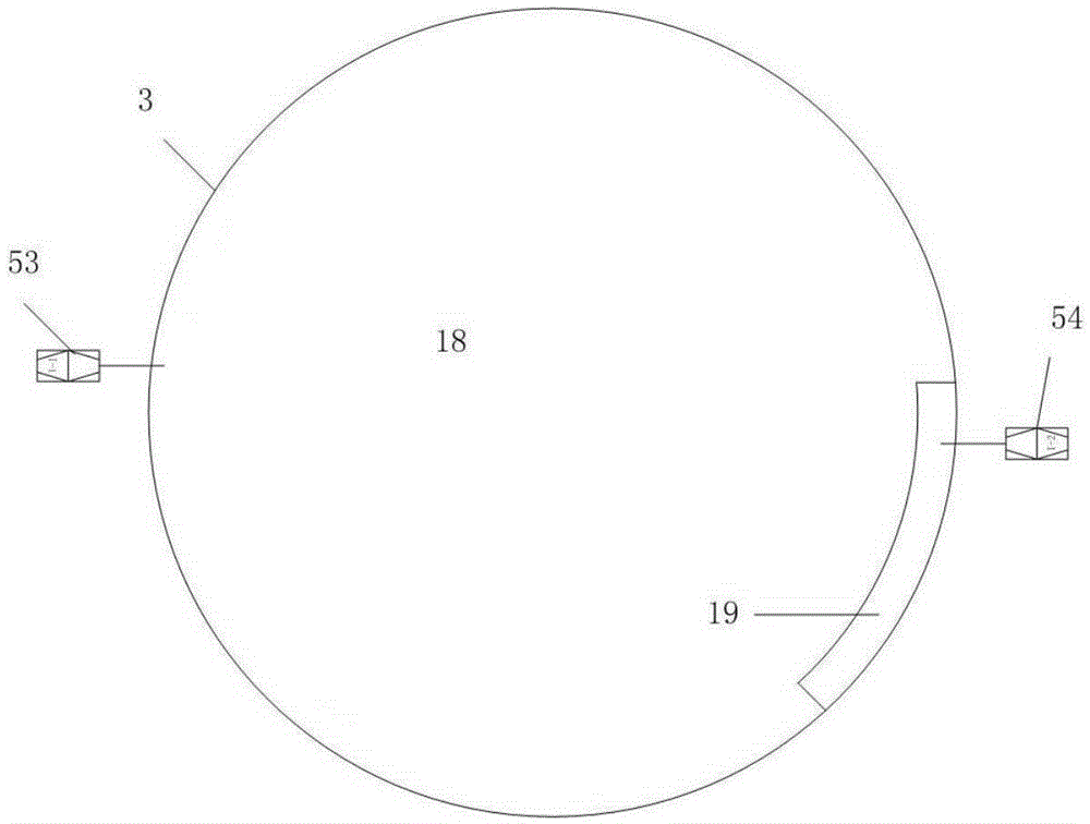
[0033] Such as figure 1 and figure 2As shown, the scour corrosion channel 1 includes a scour corrosion tank 38, a plurality of sample installation ports 9 located above the scour corrosion tank 38, a hygrometer 10 and a pH meter 12 positioned on the scour corrosion tank 38, and one located at Scouring the transparent observation window 11 on the side wall of the ...


PUM


Abstract

The invention provides a high-temperature corrosion and erosion testing device of a bent pipe column of an oil well pipe. The high-temperature corrosion and erosion testing device comprises an erosion and corrosion channel, an electrochemical work station and a storage tank, wherein the storage tank comprises a storage tank secondary cavity and a storage tank main cavity, which are arranged in sequence from bottom to top; the upper end of the storage tank secondary cavity is communicated with the upper part of the storage tank main cavity through a connection channel, and a secondary temperature controller is arranged at the bottom of the lower end of the storage tank secondary cavity; the erosion and corrosion channel comprises an erosion and corrosion box body, and the two ends of the erosion and corrosion box body are communicated with the storage tank main cavity through a main pipeline and a main loop respectively; the erosion and corrosion box body is provided with a plurality of sample mounting holes; the main pipeline is communicated with the storage tank main cavity through a gas pipeline and a liquid pipeline, which are arranged in parallel; a gas flow controller and a gas control valve are arranged on the gas pipeline connected onto the upper part of the storage tank main cavity respectively; a liquid flow controller and a liquid control valve are arranged on the liquid pipeline connected onto the lower part of the storage tank main cavity respectively; the upper end of the gas flow controller is connected with the upper end of the liquid flow controller through a communication pipeline and the communication pipeline is provided with a regulating and controlling valve; and the electrochemical work station is connected with a sample.

Description

technical field [0001] The invention relates to the field of corrosion evaluation of oil well pipe strings, in particular to a high-temperature corrosion and erosion test device for buckling pipe strings of oil well pipes. Background technique [0002] During the production of oil and gas wells, various types of corrosion will occur in the downhole pipe string, among which, the erosion effect of the high-speed fluid in the wellbore on the oil well pipe string is particularly significant. Because the high-speed fluid makes the corrosive medium (H 2 S, CO 2 , Cl - etc.) and sand and gravel on the metal surface (impact or turbulent flow), under the joint action of mechanical wear and corrosion, the corrosion is accelerated. In the process of gas well exploitation, the high-velocity gas contains water vapor, and the flow is irregular, so that the air bubbles are continuously generated and disappeared on the metal surface, and the resulting water hammer action breaks the prote...

Claims


Application Information

Patent Timeline
Patent Type & Authority Applications(China)
IPC IPC(8): G01N17/02
Inventor 朱丽娟冯春袁军涛王鹏刘永刚徐欣韩礼红王新虎
Owner BC P INC CHINA NAT PETROLEUM CORP
Why Eureka
Try Eureka