Frequency-stable solid state discharging ignition device

An ignition device and solid-state technology, applied in jet propulsion devices, gas turbine devices, machines/engines, etc., can solve the problems of unable to meet the requirements of spark frequency stability and low service life of gas discharge tubes, and achieve high electrical conversion efficiency and electrical efficiency High, the effect of reducing the size of the device

Pending Publication Date: 2019-03-01
四川泛华航空仪表电器有限公司
View PDF0 Cites 2 Cited by
  • Summary
  • Abstract
  • Description
  • Claims
  • Application Information

AI Technical Summary

Problems solved by technology

The gas discharge tube has a low service life, and the discharge is not subject to external control, which cannot meet the spark frequency stability requirements

Method used


Image

  • Frequency-stable solid state discharging ignition device
  • Frequency-stable solid state discharging ignition device
  • Frequency-stable solid state discharging ignition device

Examples


Embodiment 1

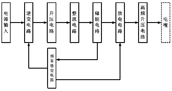
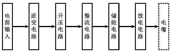
[0025] The present invention is realized through the following technical solutions, as Figure 1-Figure 2 As shown, a frequency-stabilized solid-state discharge ignition device is connected to a power input interface, including an inverter circuit, a spark frequency stabilization circuit, a boost circuit, a rectifier circuit, an energy storage circuit, a discharge circuit, and a high-frequency boost circuit; the inverter circuit, booster circuit, rectifier circuit, energy storage circuit, discharge circuit, and high-frequency booster circuit are connected in sequence, the output end of the energy storage circuit is connected to the input end of the spark frequency stabilization circuit, and the output ends of the spark frequency stabilization circuit are respectively Connect with inverter circuit and discharge circuit.

[0026] It should be noted that, through the above improvements, the present invention proposes a frequency-stabilized solid-state discharge ignition device, i...

Embodiment 2

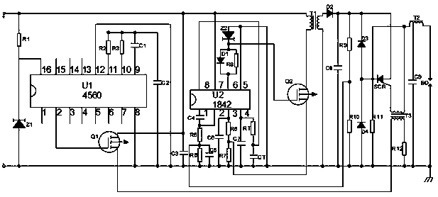
[0031] This embodiment is further optimized on the basis of the above embodiments, such as Figure 1-Figure 2 As shown, the inverter circuit includes a PWM control chip U2 and a MOS field effect transistor Q2. The PWM control chip is connected to the power input interface, and the sixth pin of the PWM control chip is connected to the gate of the MOS field effect transistor Q2. connection, the third pin of the PWM control chip is connected to the source level of the MOS field effect transistor Q2 through the resistor R6, and the drain level of the MOS field effect transistor Q2 is connected to the boost circuit;

[0032] The boost circuit includes a high-voltage silicon stack diode D1, a resistor R8, and a transformer T1, and the high-voltage silicon stack diode D1 and resistor R8 are connected in parallel between the PWM control chip U2 and the MOS field effect transistor Q2; the primary winding of the transformer T1 Connected to the drain of MOS field effect transistor Q2;

...

Embodiment 3

[0038] This embodiment is further optimized on the basis of the above embodiments, such as Figure 1-Figure 2 As shown, the discharge circuit includes a diode D3 and a thyristor SCR; the diode D3 is connected in parallel with the energy storage capacitor C8, the cathode of the thyristor SCR is connected to the anode of the diode D3, and the anode of the thyristor SCR is connected to the cathode of the high voltage silicon stack diode D2, The control pole of the thyristor SCR is connected with the spark frequency stabilization circuit;

[0039] The high-frequency boost circuit includes a high-frequency transformer T2, an oscillating capacitor C9, a diode D4, and a resistor R11; the resistor R11 and the diode D4 are connected in parallel to the cathode of the thyristor SCR and the high-frequency transformer T2 respectively, and the high-frequency transformer T2 passes through The oscillation capacitor C9 is grounded;

[0040] The spark frequency stabilization circuit includes a...


PUM


Abstract

The invention discloses a frequency-stable solid state discharging ignition device which is connected with a power input port. The frequency-stable solid state discharging ignition device comprises aninverter circuit, a spark frequency stabilizing circuit, a booster circuit, a rectifying circuit, an energy storage circuit, a discharging circuit and a high-frequency booster circuit; the inverter circuit, the booster circuit, the rectifying circuit, the energy storage circuit, the discharging circuit and the high-frequency booster circuit are connected with each other in turn; an output end ofthe energy storage circuit is connected with an input end of the spark frequency stabilizing circuit; the output end of the spark frequency stabilizing circuit is respectively connected with the inverter circuit and the discharging circuit. The frequency-stable solid state discharging ignition device is capable of solving the problems of high energy loss, uncontrollable discharge time and short service life of the traditional ignition device and has the characteristics of high efficiency, long service life and high spark frequency stability.

Description

technical field [0001] The invention relates to the technical field of aviation frequency-stabilized ignition, in particular to a frequency-stabilized solid-state discharge ignition device. Background technique [0002] In the existing technology, such as image 3 As shown, the aero-engine DC variable capacitor discharge ignition device generally consists of an inverter circuit, a boost circuit, a rectifier circuit, an energy storage circuit and a discharge control circuit. Its working principle is: the DC power supply is converted into high-voltage DC pulses in the inverter circuit and booster circuit, and stored in the energy storage capacitor after distillation; when the energy in the energy storage capacitor meets the requirements of the group, the discharge in the discharge circuit The switch is then turned on to provide a path for the energy release in the energy storage capacitor to generate a high voltage that can ionize the air. [0003] Ignition devices for aircra...

Claims


Application Information

Patent Timeline
IPC IPC(8): F02C7/266
CPCF02C7/266
Inventor 彭进田
Owner 四川泛华航空仪表电器有限公司
Why Eureka
Try Eureka