Microscopic polarization spectral analysis system and method

An analysis system and polarization spectrum technology, applied in the field of microscopic polarization spectrum analysis system, can solve the problems of high sensitivity cost, small MO activity, etc., and achieve the effects of flexible system and method, increased signal-to-noise ratio, and low system cost

Inactive Publication Date: 2019-03-01
南京昆腾科技有限公司
View PDF19 Cites 3 Cited by
  • Summary
  • Abstract
  • Description
  • Claims
  • Application Information

AI Technical Summary

Problems solved by technology

Therefore, these systems spend a lot of time in order to improve the high sensitivity of small MO activity

Method used


Image

  • Microscopic polarization spectral analysis system and method
  • Microscopic polarization spectral analysis system and method

Examples


Embodiment Construction

[0032] Below in conjunction with accompanying drawing, technical scheme of the present invention is described in further detail:

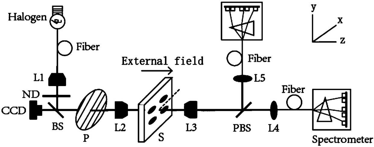
[0033] This embodiment proposes a microscopic polarization spectrum analysis system, such as figure 1 As shown, it includes a white light source, a polarizing system, a polarization analysis system and a microscopic imaging system. A sample S is set between the analysis systems, and the sample S is set in a magnetic field applied along the light propagation direction (Z axis). The polarizing system includes an optical polarizer P that can rotate around the central axis. The propagation direction (horizontal direction) of the beam in the polarizing system is defined as the z-axis, and the vertical direction perpendicular to the beam propagation direction is defined as the y-axis. The longitudinal direction perpendicular to the propagation direction of the light speed is defined as the x-axis, the optical polarizer P is arranged on the electric plat...


PUM


Abstract

The present invention provides a microscopic polarization spectral analysis system. The system comprises a white light source, a polarization system, a polarization analysis system and a microscopic imaging system. A sample is arranged between the polarization system and the polarization analysis system; the polarization system comprises an optical polarizer rotated around a center shaft; the polarization analysis system comprises a polarization beam splitter, a first spectrograph and a second spectrograph, and the polarization beam splitter is connected with the first spectrograph and the second spectrograph through optical fibers; and the microscopic imaging system comprises an objective lens arranged at the front of the sample and an imaging lens arranged at the front of a camera. The system is suitable for the whole spectral region from ultraviolet to infrared, simple to construct and can measure the magneto-optic features of the whole spectrum.

Description

technical field [0001] The invention relates to a structure analysis and optical absorption and polarization spectrum measurement technology that can be used for materials, specifically a micro polarization spectrum analysis system and method, belonging to the technical field of light polarization analysis. Background technique [0002] In 1845, Faraday discovered that the plane of polarization of linearly polarized light was rotated when it propagated through glass in a magnetic field; Kerr later found similar results in reflective devices. This phenomenon is called the magneto-optical (MO) effect, and is now widely used in magnetization imaging, magneto-optical disks, telecommunications, and current sensors. [0003] Usually, the MO activity is very small, and the Faraday rotation angle is generally less than 1°. Since the modulation amplitude depends on the size of the wavelength, the traditional system uses a modulation method based on monochromatic light. In order to ob...

Claims


Application Information

Patent Timeline
Patent Type & Authority Applications(China)
IPC IPC(8): G01J3/447
CPCG01J3/447
Inventor 杜关祥刘颖胡振忠董明明杨博陈国彬
Owner 南京昆腾科技有限公司
Why Eureka
Try Eureka