

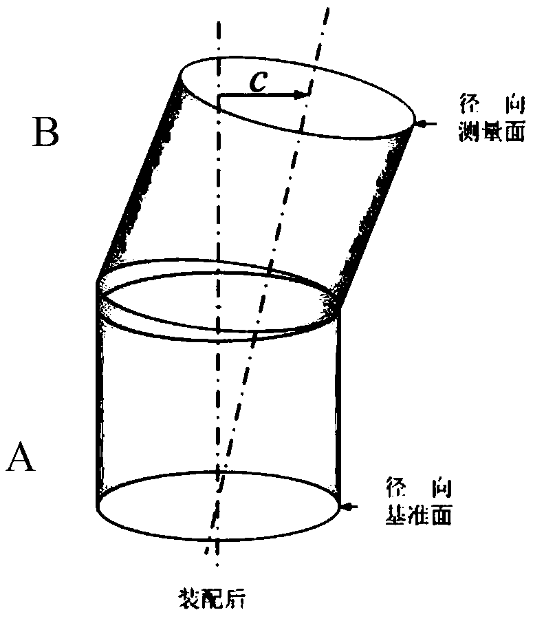
A finite element method for calculating the deflection of the assembly axis of a rotor considering contact elastic deformation
A rotor assembly and elastic deformation technology, applied in calculation, design optimization/simulation, special data processing applications, etc., can solve problems such as reducing the accuracy of algorithm prediction, achieve both analysis efficiency and accuracy, high calculation efficiency, and reduce analysis the effect of time
- Summary
- Abstract
- Description
- Claims
- Application Information
AI Technical Summary
Problems solved by technology
Method used
Image

Examples
Embodiment Construction
[0047]In order to make the purpose, technical solution and advantages of the present invention more clearly described, the following uses the rotor flange modeling corresponding to two sets of end jump data as an example to illustrate the reverse modeling process and the finite element analysis process. The accompanying drawings fully describe the technical solutions in the present invention.
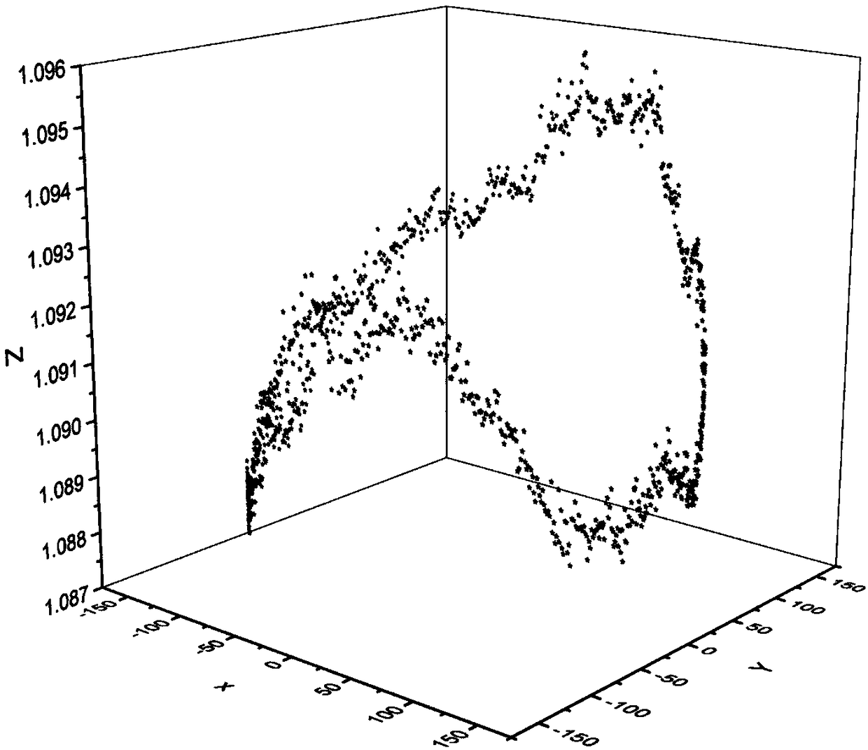
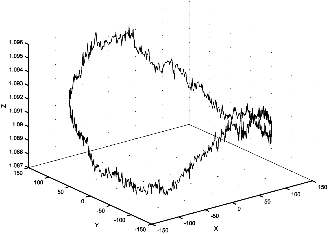
[0048] (1) The cylindricity-waviness measuring instrument is used here to obtain two sets of end jump data, namely D01.xls and D02.xls, and save them to the search path of matlab.
[0049] In order to make the overall outline of the end surface runout data more intuitive, the first set of end runout data is expressed in the form of coordinate points, so that the ups and downs of the shape points can be seen, such as figure 2 As shown, the end-jump data in the two sets of cylindrical coordinate systems are converted into data points in the rectangular coordinate system, and the data poi...
PUM
 Abstract
Description
Claims
Application Information