Device and method applied to ion beam etching sputtering protection

A technology of ion beam etching and scribing, which is applied in the direction of circuits, discharge tubes, electrical components, etc., can solve the problems of poor uniformity, out-of-tolerance etching groove depth of thrust plate, splash, and finally impact from different angles, etc., to achieve Ensure consistency, good uniformity, and avoid the effect of etching groove depth out of tolerance

Active Publication Date: 2019-03-01
TIANJIN NAVIGATION INSTR RES INST
View PDF5 Cites 1 Cited by
  • Summary
  • Abstract
  • Description
  • Claims
  • Application Information

AI Technical Summary

Problems solved by technology

After the ion flow enters the vacuum chamber, most of it is directly shot at the target material of the workpiece table, and has a frontal impact on the thrust plate on the workpiece table, but some of the ion flow will splash in the vacuum chamber in a disordered state, and finally from Impacting the thrust plate at different angles, due to the disordered and irregular impact angle and speed, is the biggest factor causing the depth of the etched groove of the thrust plate to be out of tolerance and poor in uniformity

Method used


Image

  • Device and method applied to ion beam etching sputtering protection
  • Device and method applied to ion beam etching sputtering protection
  • Device and method applied to ion beam etching sputtering protection

Examples


Embodiment Construction

[0022] The embodiments of the present invention will be described in detail below in conjunction with the accompanying drawings. It should be noted that the embodiments are illustrative, not restrictive, and cannot limit the protection scope of the present invention.

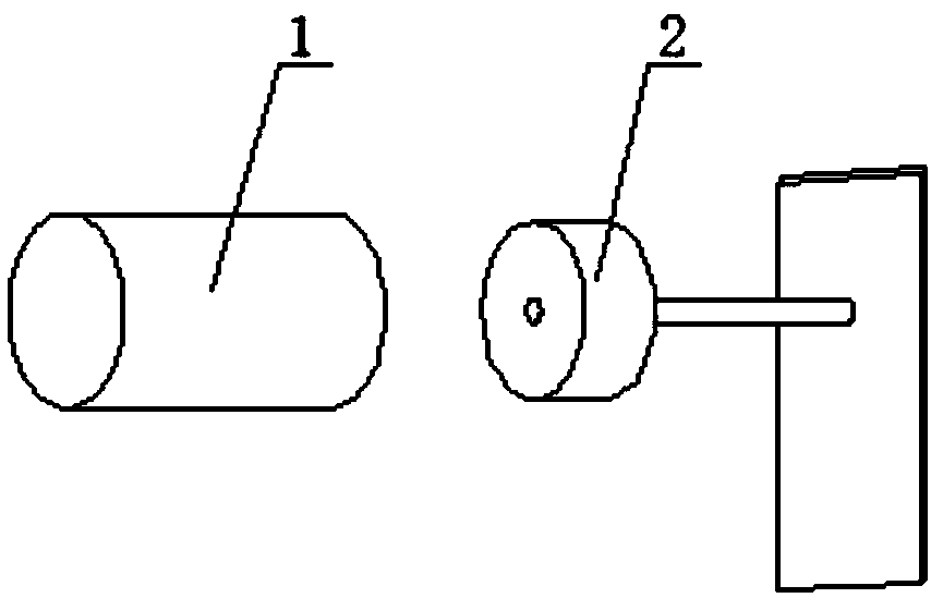
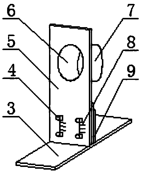
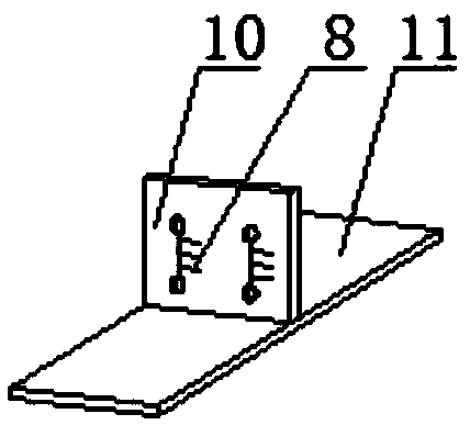
[0023] Such as figure 2 -- Figure 4 As shown, a device applied to ion beam etching and sputtering protection includes a front support 5, a base support 3 and a cylindrical shielding tube 7, the front support is vertically arranged, and the lower part of the front support is installed on the base support. The structure is: the base support includes a base plate 11 and a vertical plate 10, the vertical plate is vertically installed on the base plate, and the vertical plate is fixedly connected with the bottom of the front support through a pressing plate 9 and screws 4. Both the front bracket and the base bracket are provided with engraved lines 8, and the position of the cylindrical shielding cylinder can be a...


PUM


Abstract

The invention relates to a device and method applied to ion beam etching sputtering protection. The device mainly comprises a cylindrical shielding cylinder and a base support, wherein the cylindricalshielding cylinder is arranged on a front-surface support. The device is integrally arranged in a vacuum chamber cabin door and is in right front of a workbench, the position of the cylindrical shielding cylinder can be adjusted by the base support and the front-surface support, so that the cylindrical shielding cylinder and a push stop plate of the workbench are arranged on the same horizontal surface; and after the push stop plate is arranged at a target of the workbench, sputtering protection is performed on the push stop plate, so that deep tolerance of an etching push stop plate caused by ion sputtering during the ion beam etching process is reduced, and the accuracy requirement of a gyro is met.

Description

technical field [0001] The present invention relates to the technical field of ion beam etching, in particular to a device and method for ion beam etching sputtering protection, the main purpose of which is to reduce the etching thrust caused by ion sputtering in the ion beam etching process The depth of the plate groove is out of tolerance. Background technique [0002] The gyroscope uses a dynamic pressure air bearing motor, and the motor thrust plate is a key part of the thrust bearing. The uniformity of the groove depth of the spiral groove is an important parameter to realize an effective air bearing, which directly affects the support performance and operation stability of the motor. At present, the helical groove of the thrust plate of the gyroscope motor is processed by ion beam etching. [0003] The essence of ion beam etching is a processing method in which high-energy ion flow hits the surface of the part, and the atoms hit by the hit are separated from the body ...

Claims


Application Information

Patent Timeline
IPC IPC(8): H01J37/30H01J37/305
CPCH01J37/3002H01J37/3053
Inventor 郑林石慧王殿良崔云涛吴洪文王得信
Owner TIANJIN NAVIGATION INSTR RES INST
Why Eureka
Try Eureka