Electric motor drive device
A driving device and motor technology, which is applied in the direction of electrical devices, circuit devices, AC motor control, etc., can solve the problems of reducing the capacity of smoothing capacitors, achieve miniaturization, realize the device structure, and suppress the effect of voltage rise
- Summary
- Abstract
- Description
- Claims
- Application Information
AI Technical Summary
Problems solved by technology
Method used
Image
Examples
Embodiment approach 1
[0040] Next, Embodiment 1 of the present invention will be described.
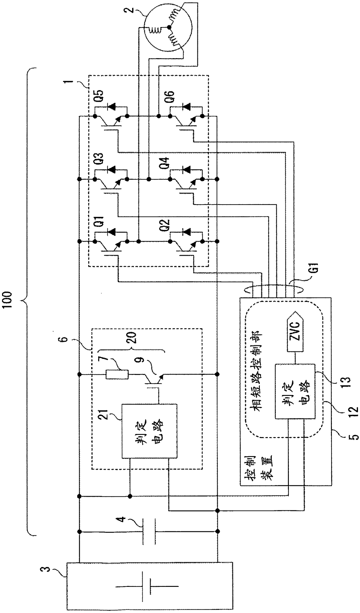
[0041] figure 1 It is a diagram showing a schematic configuration of the motor drive device according to Embodiment 1 of the present invention.
[0042] Such as figure 1 As shown, the motor drive device 100 converts the DC power from the DC power supply 3 into AC power through the inverter 1 and drives the motor 2. The control device 5 of the device 1, and the overvoltage protection unit 6. In addition, the electric motor 2 can perform both a driving operation and a regenerative operation.
[0043] The inverter 1 is a three-phase bridge circuit composed of IGBTs (Insulated Gate Bipolar Transistor, insulated gate bipolar transistors) Q1 to Q6 as semiconductor switching elements in which diodes are connected in antiparallel, and converts the DC power of the smoothing capacitor 4 into Three-phase AC power and drives the motor 2. In addition, the semiconductor switching elements Q1 to Q6 constituting the ...
Embodiment approach 2
[0120] Next, Embodiment 2 of the present invention will be described. Figure 9 It is a figure which shows the schematic structure of the motor drive apparatus 100a which concerns on Embodiment 2 of this invention.
[0121] In Embodiment 2, the overvoltage protection unit 6 is integrated with the control device 5a. This assumes that the first determination circuit 21 can be arranged close to the voltage measurement point on the main circuit by integrating the inverter 1 and the control device 5a or the like. The other configurations are the same as those of the above-mentioned first embodiment, and the same operation is performed.
[0122] In the second embodiment, since the first determination circuit 21 and the second determination circuit 13 are configured independently, the same effects as those in the first embodiment described above can be achieved.
Embodiment approach 3
[0124] Next, Embodiment 3 of the present invention will be described. Figure 10 It is a figure which shows the schematic structure of the motor drive apparatus 100b which concerns on Embodiment 3 of this invention.
[0125] Such as Figure 10 As shown, the motor drive device 100b drives two motors 2a, 2b, and includes two inverters 1a, 1b that drive the respective motors 2a, 2b. In addition, a smoothing capacitor 4 connected in parallel to the DC power supply 3 , a control device 5 b for controlling the inverters 1 a and 1 b , and an overvoltage protection unit 6 are provided. Moreover, each electric motor 2a, 2b can perform both a drive operation and a regenerative operation.
[0126] The inverters 1a, 1b have the same configuration as the inverter 1 of the first embodiment, and the control device 5b generates gate signals G1a, G1b to control the power running operation and regenerative operation of the inverters 1a, 1b.
[0127] In this case, the maximum regenerative pow...
PUM
 Abstract
Description
Claims
Application Information
 - R&D
- Intellectual Property
- Life Sciences
- Materials
- Tech Scout
- Unparalleled Data Quality
- Higher Quality Content
- 60% Fewer Hallucinations
Browse by: Latest US Patents, China's latest patents, Technical Efficacy Thesaurus, Application Domain, Technology Topic, Popular Technical Reports.
© 2025 PatSnap. All rights reserved.Legal|Privacy policy|Modern Slavery Act Transparency Statement|Sitemap|About US| Contact US: help@patsnap.com


