Novel pneumatic hydraulic synchronous clamp device

A pneumatic hydraulic and fixture device technology, applied in the direction of clamping device, positioning device, clamping, etc., can solve the problems of inability to automatically locate the center positioning accuracy of the workpiece, reduce the qualified rate of workpiece processing, waste manpower and material resources, etc., so as to improve the processing qualification. High efficiency, high repeat positioning accuracy, cost reduction effect

Inactive Publication Date: 2019-03-05
泉州市创佳自动化设备有限公司
View PDF5 Cites 1 Cited by
  • Summary
  • Abstract
  • Description
  • Claims
  • Application Information

AI Technical Summary

Problems solved by technology

[0003] However, in the clamping process of existing fixtures, the grippers are not synchronized, the accuracy is not high, and there are disadvantages such as the inability to automatically locate the center of the workpiece or low positioning accuracy, which reduces the qualified rate of workpiece processing and wastes a lot of manpower and material resources

Method used


Image

  • Novel pneumatic hydraulic synchronous clamp device

Examples


Embodiment Construction

[0015] The present invention will be further described in conjunction with the accompanying drawings and specific embodiments.

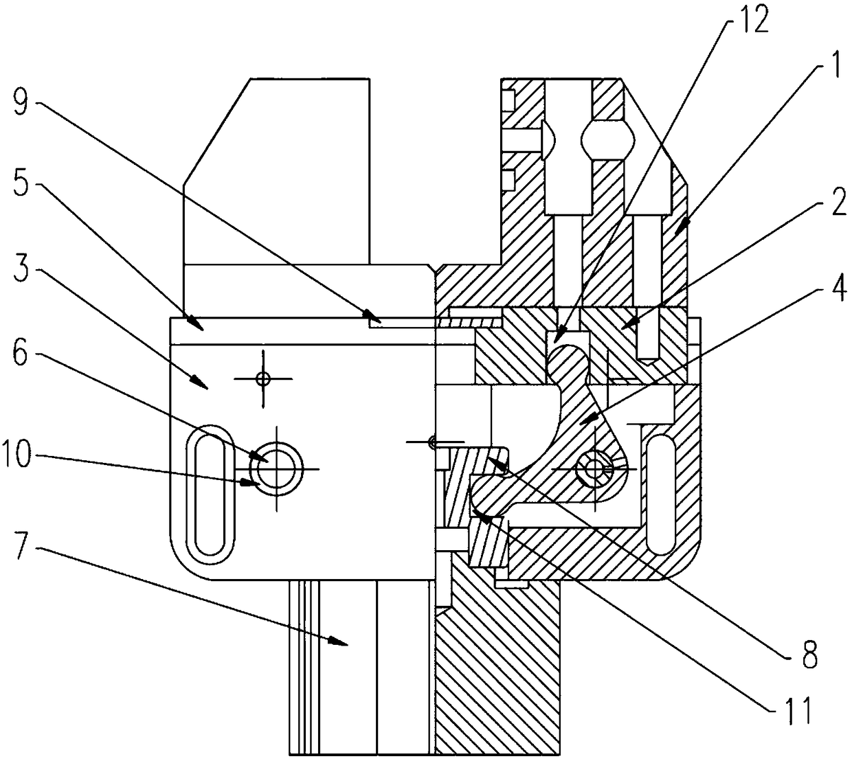
[0016] refer to figure 1 , the embodiment of the present invention discloses a new type of pneumatic-hydraulic synchronous clamping device, including a clamping block 1, a slider 2, a clamping base 3, a triangular lever 4, a horizontal pressing plate 5, a pin 6, a pressure cylinder 7, a piston 8, a horizontal anti- The dust plate 9 and the fixed shaft sleeve 10, a cavity is provided in the clamp base 3, and a piston 8 that can reciprocate up and down along the shaft is installed coaxially in the cavity of the clamp base 3, and the piston 8 The lower part of the lower part is connected with the pressure cylinder 7 installed under the fixture base 3. The pressure cylinder 7 provides power for the reciprocating movement of the piston 8. In this embodiment, the transmission connection between the pressure cylinder 7 and the piston 8 is known and commonly...


PUM


Abstract

The invention provides a novel pneumatic hydraulic synchronous clamp device which comprises clamping blocks, sliding blocks, a clamp base, triangle levers, a horizontal pressing plate, a pin shaft, apressure cylinder, a piston, a horizontal dustproof plate and a fixing shaft sleeve. A containing cavity is formed in the clamp base. A piston capable of moving up and down along the shaft in a reciprocating manner is coaxially installed in the containing cavity of the clamp base. The lower portion of the piston is in transmission connection with the pressure cylinder installed below the clamp base. The triangle levers are connected to the left side and the right side of the piston correspondingly. The sliding blocks capable of moving left and right in a reciprocating manner are connected above the triangle levers. One clamping block is fixed to each sliding block. The horizontal pressing plate connected with the clamp base is further arranged between the sliding blocks and the clamping blocks. According to the lever principle, the pressure cylinder is utilized for moving up and down to pull the levers to control the left sliding block and the right sliding block to move in the same direction or the opposite directions, and it is ensured that the center is located automatically for clamping a workpiece.

Description

technical field [0001] The invention belongs to a clamp, in particular to a novel pneumatic-hydraulic synchronous clamp device. Background technique [0002] A fixture is a device used to fix the processing object in the process of mechanical manufacturing so that it occupies the correct position for construction or inspection. In a broad sense, any process in the process, the device used to install the workpiece quickly, conveniently and safely, can be called a fixture. Such as welding fixtures, inspection fixtures, assembly fixtures, machine tool fixtures, etc. Among them, machine tool fixtures are the most common, often referred to as fixtures. When processing a workpiece on a machine tool, in order to make the surface of the workpiece meet the technical requirements such as the size, geometric shape, and mutual position accuracy with other surfaces specified in the drawing, the workpiece must be installed (positioned) and clamped (clamped) before processing. . The fi...

Claims


Application Information

Patent Timeline
Patent Type & Authority Applications(China)
IPC IPC(8): B23Q3/00
CPCB23Q3/00B23Q2703/04
Inventor 王国金
Owner 泉州市创佳自动化设备有限公司
Why Eureka
Try Eureka