
Current sensor easy to install and with magneto-electric composite material

A magnetoelectric composite material and current sensor technology, applied in the direction of measuring current/voltage, instruments, measuring devices, etc., can solve problems such as difficulty in ensuring the complete closure of the magnetic gathering ring, limiting the scope of application, etc., to achieve stable and reliable measurement results and wide application range Wide, high-resolution effects

Active Publication Date: 2019-03-05
NANJING UNIV OF SCI & TECH
View PDF7 Cites 11 Cited by
  • Summary
  • Abstract
  • Description
  • Claims
  • Application Information

AI Technical Summary

Problems solved by technology

However, the Hall element is an active device, and a bias voltage must be applied to ensure its normal operation during use, which greatly limits its scope of application.
[0005] Most sensors have two installation holes, and the distance between the two installation holes remains unchanged, which also puts forward higher position requirements for the holes on the base; there are also sensors with a split structure on the market, but It is difficult for this type of sensor to ensure the complete closure of the magnetic gathering ring after repeated opening and closing

Method used


Image

  • Current sensor easy to install and with magneto-electric composite material
  • Current sensor easy to install and with magneto-electric composite material
  • Current sensor easy to install and with magneto-electric composite material

Examples


Embodiment

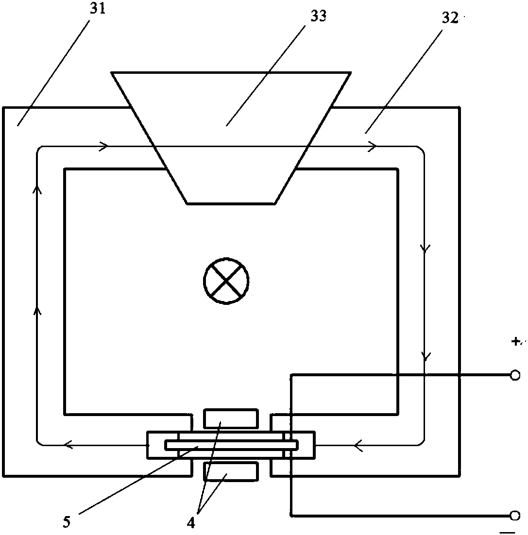
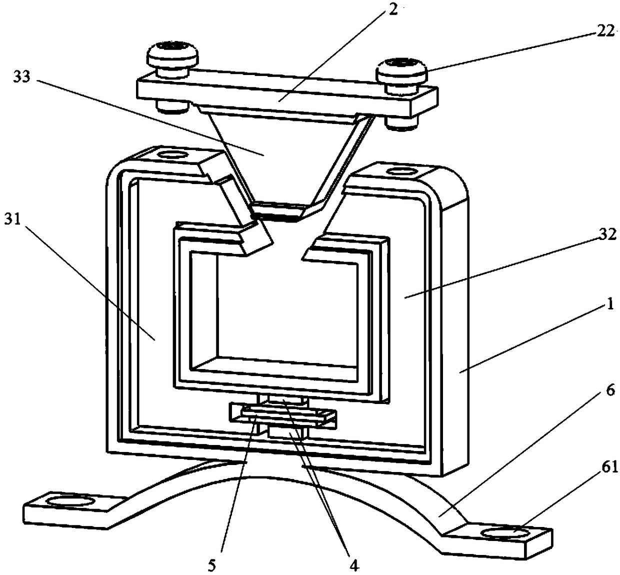
[0031] figure 1 It is a schematic diagram of the principle of the sensor. The current-carrying wire passes through the magnetic ring. According to the magnetic effect of the current, a circular magnetic field is generated around the wire. The magnetic ring is composed of a high magnetic permeability core 1 and a high magnetic permeability core 2 32. Three high-permeability magnetic cores 33 are formed. The ends of the high-permeability magnetic core one 31 and the high-permeability magnetic core two 32 are matched with grooves. The sensitive element 5 applies the annular magnetic field, the magnetostrictive material layer in the sensitive element 5 generates strain under the action of the magnetic field, and the mechanical motion is transmitted to the piezoelectric ceramic material layer through the bonding layer, and the piezoelectric ceramic material layer feels the strain And output a proportional voltage signal.

[0032] In this embodiment, the sensitive unit 5 is bonded ...


PUM


Abstract

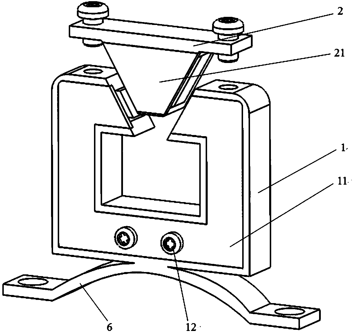
The invention provides a current sensor easy to install and with a magneto-electric composite material. The current sensor comprises a magnet ring formed by assembling magnetic cores, and a sensitivecomponent composed of a magnetostrictive material layer and piezoelectric ceramic material layers arranged in the two sides of the magnetostrictive material layer respectively; an electrode in the endportions of the piezoelectric ceramic material layers is connected with the signal processing circuit via a lead; the signal processing circuit processes a voltage signal output by the piezoelectricceramic material layers and then sends the processed signal to external equipment for display, the bottom of the sensor is provided with a bearer which includes an elastic thin metal sheet which is bent to an arc shape; installation portions in the two ends of the bearer are provided with installation holes respectively; and the when the bearer bears a pressure, the arc-shaped thin metal sheet isdeformed, and thus, distance between the two installation holes is adjusted. The current sensor is high in stability and resolution, simple in operation and wide in suitable range.

Description

technical field [0001] The invention belongs to the technical field of electronic detection equipment manufacturing, in particular to a current sensor. Background technique [0002] Traditional current sensors mainly include shunts, current transformers, Hall current sensors and other devices. The shunt is a resistive element specially used for current measurement, which can measure DC and MHz-level alternating current. However, when the shunt is used, it needs to be connected in series to the circuit, which belongs to contact measurement. On the one hand, the installation of the sensor is very inconvenient, which affects the efficiency of use. On the other hand, because the shunt needs to be connected to the circuit to perform measurement, this makes Part of the power will be wasted in the form of heat energy due to the heating of the resistor, and it is difficult to guarantee personal safety. [0003] A current transformer is generally composed of a closed soft magnetic ...

Claims


Application Information

Patent Timeline
Patent Type & Authority Applications(China)
IPC IPC(8): G01R19/00G01R3/00
CPCG01R3/00G01R19/00
Inventor 卞雷祥钟名尤
Owner NANJING UNIV OF SCI & TECH
Learn More