Tripolar magnetic coupling mechanism applied in rail traffic wireless power supply system

A technology for wireless power supply and rail transit, applied in charging stations, motor vehicles, electric vehicles, etc., can solve problems such as serious electromagnetic radiation and large leakage magnetic field, and achieve good electromagnetic compatibility, small electromagnetic radiation, and improved system efficiency

Active Publication Date: 2019-03-08
HARBIN INST OF TECH
View PDF6 Cites 3 Cited by
  • Summary
  • Abstract
  • Description
  • Claims
  • Application Information

AI Technical Summary

Problems solved by technology

[0005] The purpose of the present invention is to solve the problems of large magnetic field leakage and serious electromagnetic radiation in the magnetic coupling mechanism currently used in the rail transit wireless power supply system, and to provide a three-pole magnetic coupling mechanism applied to the rail transit wireless power supply system

Method used


Image

  • Tripolar magnetic coupling mechanism applied in rail traffic wireless power supply system
  • Tripolar magnetic coupling mechanism applied in rail traffic wireless power supply system
  • Tripolar magnetic coupling mechanism applied in rail traffic wireless power supply system

Examples


Embodiment Construction

[0026] The technical solutions in the embodiments of the present invention will be clearly and completely described below in conjunction with the accompanying drawings in the embodiments of the present invention. Obviously, the described embodiments are only some of the embodiments of the present invention, not all of them. Based on the embodiments of the present invention, all other embodiments obtained by persons of ordinary skill in the art without making creative efforts belong to the protection scope of the present invention.

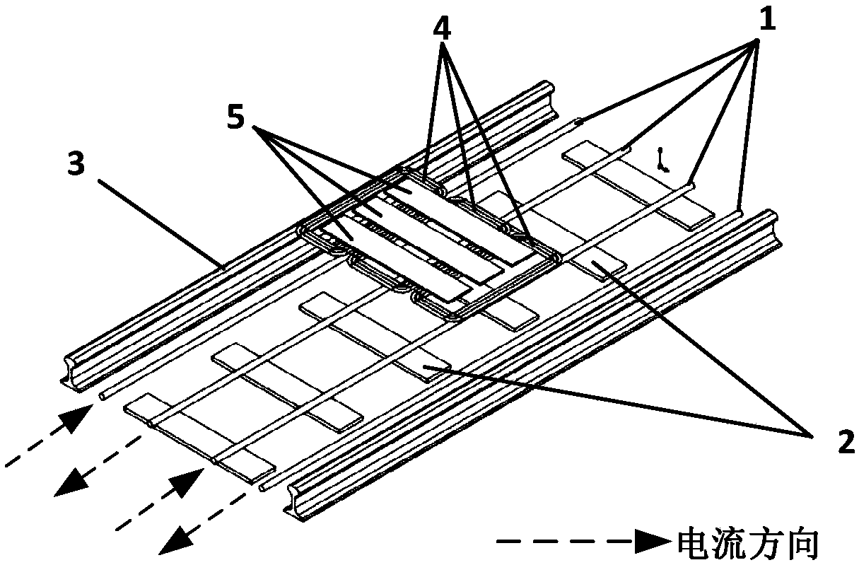
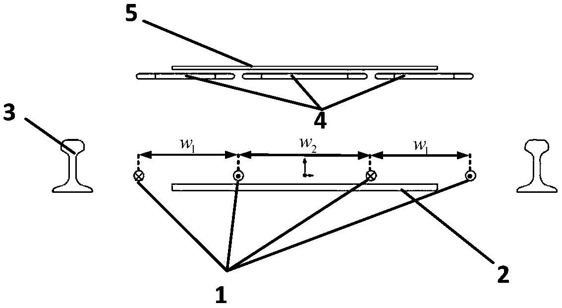
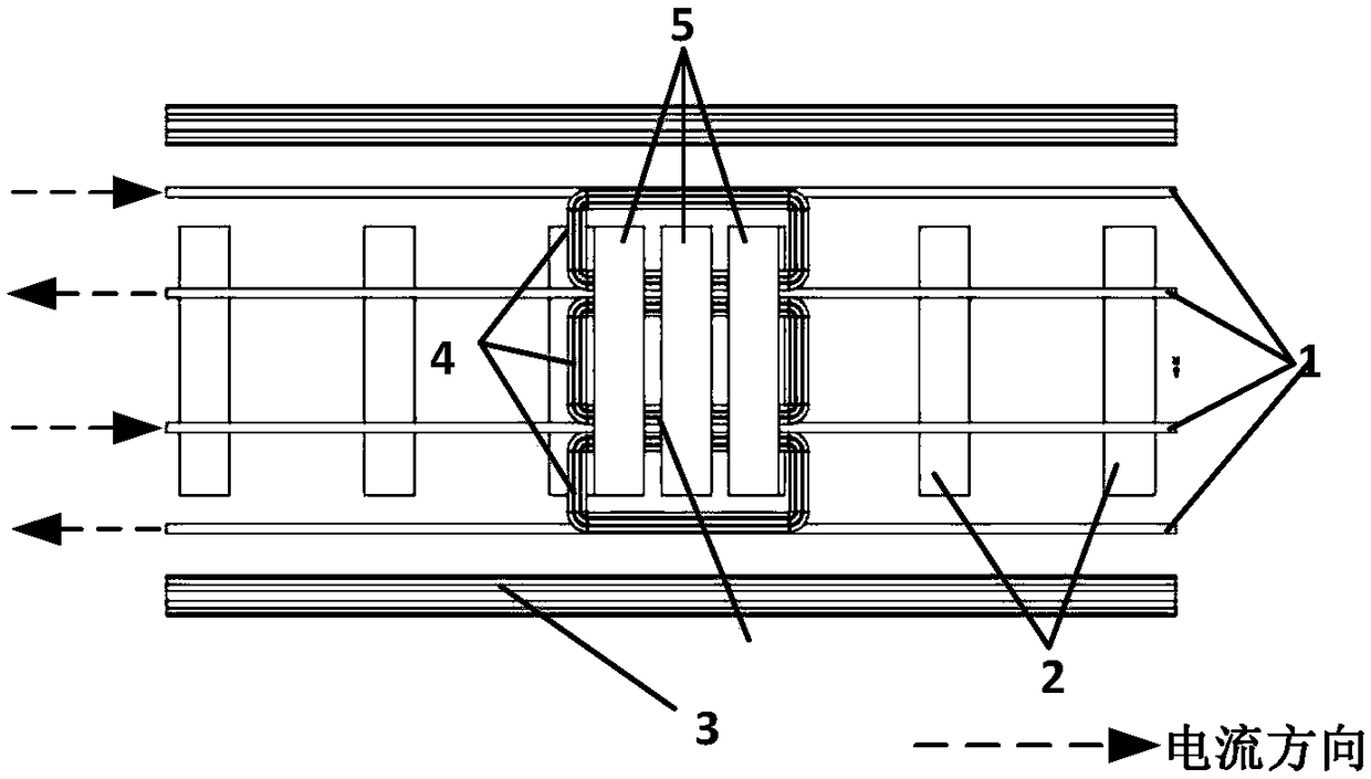
[0027] combine Figure 1-Figure 5 , the present invention proposes a three-pole magnetic coupling mechanism applied to a rail transit wireless power supply system. The three-pole magnetic coupling mechanism is composed of two parts, one part is a power supply guide rail for transmitting electric energy, and the other part is for receiving An electrical energy receiving device for electrical energy;

[0028] The power supply guide rail is laid on t...


PUM


Abstract

The invention provides a tripolar magnetic coupling mechanism applied in a rail traffic wireless power supply system. The tripolar magnetic coupling mechanism is composed of a power supply guide railfor emitting electric energy and an electric energy receiving device for receiving the electric energy. Compared with existing magnetic coupling mechanisms, the tripolar magnetic coupling mechanism has the advantages that little electromagnetic radiation is generated, electromagnetic compatibility is high, eddy loss of a leakage magnetic field in a rail in actual application is low, system efficiency is improved, and no radiation damage is caused to working personnel around the rail.

Description

technical field [0001] The invention belongs to the technical field of wireless power transmission, in particular to a three-pole magnetic coupling mechanism applied to a rail transit wireless power supply system. Background technique [0002] With the successful promotion of high-speed rail in the world, high-speed or even ultra-high-speed trains have become the focus of future rail transit research. At present, rail trains mostly use the pantograph to obtain electricity from the catenary grid. With the increase of train speed, the friction between the pantograph and the catenary grid increases rapidly, which not only increases the mechanical friction loss, but also makes the The pantograph produces strong vibrations, which increases the off-line rate, thereby significantly reducing the quality of the flow and affecting the normal running of the train. Therefore, the way of wired power supply limits the development of rail transit to high speed. [0003] Compared with the...

Claims


Application Information

Patent Timeline
Patent Type & Authority Applications(China)
IPC IPC(8): B60L53/12
CPCB60L2200/26Y02T10/70Y02T10/7072Y02T90/14
Inventor 董帅宋贝贝高鑫崔淑梅朱春波
Owner HARBIN INST OF TECH
Why Eureka
Try Eureka